Table of Contents
Advertisement
Advertisement
Table of Contents

Summary of Contents for Ironton 45406
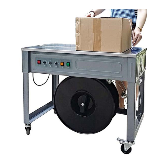
- Page 1 HIGH TABLE SEMI-AUTOMATIC STRAPPING MACHINE USER’S MANUAL WARNING: Read carefully and understand all ASSEMBLY AND OPERATION INSTRUCTIONS before operating. Failure to follow the safety rules and other basic safety precautions may result in serious personal injury. Item# 45406...
-
Page 2: Table Of Contents
Thank you very much for choosing an Ironton™ product. For future reference, please complete the owner’s record below: Model: _______________ Purchase Date: _______________ Save the receipt, warranty and these instructions. It is important that you read the entire manual to become familiar with this product before you begin using it. -
Page 3: Technical Specifications
TECHNICAL SPECIFICATIONS Item Description Packing Speed <3 second/cycle Min Package 2in. Tension Force 6.6lbs.-154lbs. (3kgs -70kgs) Width of PP Strap 0.24in.–0.6in. (6-15mm), preset at 12mm Thickness of PP Strap 0.02in.-0.0335in. (0.5mm-0.85mm) Power Voltage AC110V Power Frequency 60HZ Single phase Power two DC motors: 90W + 60W Motor HP 1/5 HP... - Page 4 Do not place the machine on the slant place. Do not move the machine when machine is running. Do not place the machine on the wet or dusty place. Keep it clean and dry. Properly ground the machine before operation. There is danger of electric shock when it does not connect to the ground wire or does not connect fully.
-
Page 5: Installation
Warning Sign 2 ③ Warning sign 3 indicates that the inner gearing parts can easily clamp hands. Keep your hands away from the parts with this label. Before maintenance, stop the machine and disconnect the plug. Warning Sign 3 NOTE: Read the other signs carefully when operating to ensure safe and correct operation and to avoid danger. INSTALLATION One set of tools and spare parts is packed with each machine for use in making adjustments and for replacement of parts as needed. -
Page 6: Start-Up
Fig. 1 Installation Dimension START-UP 1. INTRODUCTION TO THE CONTROL PANEL The control panel is at the upper right corner of the machine front plate (see Fig.2). Fig. 2 Control Panel (1) Power switch Turn on the switch (position I), then the red light is on and you can operate the machine. Turn off the switch (position O), cut down the power, then the machine stops. - Page 7 (5) Manual start button Manually start LS4 switch, the same function as PP strap interpolation. (6) Manual feeding button Press this button when the green light is on, the straps can be fed manually. While retracting strap, press this button will reset the machine. NOTE: This machine can automatically switch off after a while of inactivity and restart as the strap is inserted.
-
Page 8: Operation
3. FEEDING STRAPS (as shown in Fig. 4) Fig.4 Feeding strap WARNING: Before feeding the strap, make sure that the machine is turned off and the cord plug is pulled off from the electric outlet. 1. Pull the PP strap end until about 1 meter (3 feet) straps are off the reel. 2. -
Page 9: Adjustment Instructions
3. Connect power plug to power source (AC 110V, 60Hz). 4. Turn on the power switch and run the machine for 15 seconds to warm up to the operating temperature. 5. Place package on the table top, directly above the sealing head. Allow the package to contact the two package stops. -
Page 10: Electrical Description
ELECTRICAL DESCRIPTION A circuit diagram of the electrical description is illustrated as below. See Fig. 7. Schematic circuit diagram Fig. 7 Schematic circuit diagram Page 8 of 26... - Page 11 Below are functions of each main micro switch on circuit. LS1: It is at the right hand of Motor M1, refer to Fig. 8. The contact point will be pushed by cam of micro-switch when the machine is set to zero. LS2: It is beside LS1.
-
Page 12: Parts Cleaning
PARTS CLEANING 1. UPPER SLIDE Always keep the upper slide well fitted with both press bars, and keep it move smoothly. Thus it is important to keep the upper slide clean. Do the cleaning following the instructions below. Refer to Fig. 9. Remove the pull springs on the swaying rocker. -
Page 13: Maintenance And Lubrication
reassemble the middle knife. LS 2 LS 1 中刀 后顶刀 Rear point knife Middle point knife 前顶刀 Front point knife Adjustment 调整 Fig. 10 Knifes MAINTENANCE AND LUBRICATION The machine requires periodic maintenance and lubrication. Do not keep the product in the wet and moist place in order to prevent the danger of fine or electrical damage. - Page 14 Check if the temperature of electric heating head has changed. Check if the belt has worn. Check if the spring force is correct. 3. Once of half a year (or strap 600000 times cycles) Check the heating mechanism, change them if it is the possibility. Check if the connection parts of PC board are reliable.
-
Page 15: Troubleshooting
TROUBLESHOOTING Warning: Please make sure turn the switch to 『O』(OFF) position. Pull out the plug and screwing out the bolts that fix the table panel. Open the panel to adjust. It may occur shock or hurt caused by machine start. Screw up the bolt and then get through power supply. Trouble Cause Troubleshooting... -
Page 16: Drawing & Part List
DRAWING AND PART LIST Chart 1 Knife and skateboard assembly WARNING All parts must be periodically inspected and replaced if worn or broken.Failure to do this can affect a tool's operation and present a safety hazard. 4-DP612 DT05 4-SY616 3-DT05 DT04 ML05 DT05... - Page 17 Chart 1 Knife and skateboard assembly Code Description AS1-11 1# knife combination AS1-12 2# knife combination AS1-13 3# knife combination A0200 Mechanism base A0173 Right press bar A0172 Left press bar A0171 Up skateboard A0191 Up skateboard barrier sheet A0192 Skateboard extension spring A0205 Out with adjusting block...
- Page 18 Chart 2 Cam and reduction gear box assembly 4-SY620 4-SY620 2-SP412 2-DT03 2-SY330 4-DP38 2-DT04 Chart 2 Cam and reduction gear box assembly Page 16 of 26...
- Page 19 Chart 2 Cam and reduction gear box assembly Code Description EA012 DC cam motor A0150 Gear box cover A0152 Transition gear wheel A0151 Output gear wheel A0135 Cam shaft DJ172912 Cushion ring φ17*29*12 DJ17298 Cushion ring φ17*29*8 DJ17296 Cushion ring φ17*29*6 DW17295 Cushion ring φ17*29*0.5 A0208...
- Page 20 Chart 3 Feeding and retracting strap assembly 4-SY620 2-SY616 Chart 3 Feeding and retracting strap assembly Page 18 of 26...
- Page 21 Chart 3 Feeding and retracting strap assembly Code Description Seat belt machine A0180 Gear cover A0181 A0182 Reduction gear Eccentric shaft A0184 A0183 Send pulley Iron gear A0220 Driven wheel A0221 Band road A0186 Adjustment board A0105 Band road cover A0188 A0187 Under band road...
- Page 22 Chart 4 Machine frame 2-DT05 8-DT08 8-DP816 2-SY512 4-DT06 4-SY612 Chart 4 Machine frame Page 20 of 26...
- Page 23 Chart 4 Machine frame Code Description A0010 AS-50 frame A0011 AS-50 stainless steel table panel Arch support AS1-611 Cover support protruding sleeve AS1-612 A0090 Stainless steel iron blocking device Guide strap pulley AS1-614 A0014 pulley rack Guide strap pulley shaft AS1-615 A0016 Angle iron legs tube...
- Page 24 Chart 5 Strap reel and brake assembly SJ56 SY620 2-ZC6003K ML04 SY416 4-SS616 4-SS612 KS10 8-MLD06 KS10 KE05 Chart 5 Strap reel and brake assembly Page 22 of 26...
- Page 25 Chart 5 Strap reel and brake assembly Code Description A0061 Outside strap reel A0060 Inside strap reel A0402 Brace claw A0050 AS-50 strap reel shaft AS1-709 strap reel handle AS1-801 Brake rod pulley AS1-802 Brake pulley AS1-803A Brake rod roller wheel support AS1-814 Brake belt A0015...
- Page 26 Chart 6 Electrical parts 2-SD412 Chart 6 Electrical parts Page 24 of 26...
- Page 27 Chart 6 Electrical parts Code Description APC-10N1 PC board combination, APC-10N1 ED001 150W switch power supply Electrical box cover A0013 EF001 Micro fan 24VDC EK002 Red switch EP002 Potentiometer 250K UN001 Rotate button (black) EN001 Green button EN002 Yellow button UN002 Rotate button (red) EF001...
- Page 28 WARRANTY 1-year limited warranty Distributed by: Northern Tool + Equipment Co., Inc. Burnsville, Minnesota 55306-6936 NorthernTool.com Made in China Page 26 of 26...
Need help?
Do you have a question about the 45406 and is the answer not in the manual?
Questions and answers