Advertisement
Advertisement
Table of Contents

Related Manuals for Skrydstrup R&D MR10

Summary of Contents for Skrydstrup R&D MR10
- Page 1 SKRYDSTRUP R&D because performance ma ers Owner’s Manual MR10 Loop System...
- Page 2 This manual will introduce you to the MR10 Loop System and its features. A er reading this manual please keep it for future reference. We are confi dent that you very quickly will be familiar with the MR10 Loop System, and appreciate the versa lity and high quality of this unit.
-
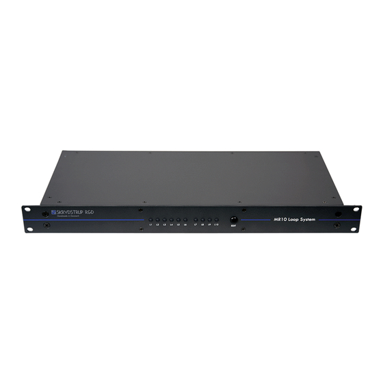
Page 3: Front Panel
When the mini toggle switch is set to LINK, the output is disabled. LOOP 1 IN: 1/4” mono jack used to provide input to the MR10 Loop System. This input u lizes our highly recognized high impedance input buff er. TUNER OUT: 1/4”... - Page 4 MIDI CONTROL ASSIGNMENTS HOW TO EDIT THE MIDI CHANNEL: - Unplug the power from the MR10 Loop System. - Press the EDIT bu on and hold it while connec ng power to the unit. - Press the EDIT bu on repeatedly un l the desired MIDI channel is selected. Look at the MIDI channel diagram below.
- Page 5 TECHNICAL SPECIFICATIONS: Power requirements: 9VAC 650mA Dimensions: 482mm x 44mm x 200mm (WxHxD) Input impedance Loop 1: 1 Mohm Input Impedance Loop 7: 1 Mohm Output impedance Loop 6: < 100 ohm Output impedance Loop 10: < 100 ohm Output impedance SEND: <...
Need help?
Do you have a question about the MR10 and is the answer not in the manual?
Questions and answers