Table of Contents
Advertisement
Advertisement
Table of Contents

Summary of Contents for ADWA AD8000
-
Page 1: User Manual
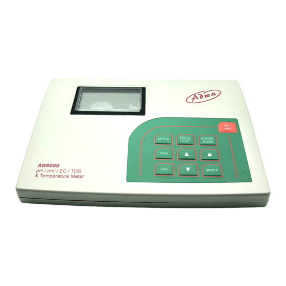
USER MANUAL AD8000 pH/mV/EC/TDS/Temperature Bench Meter ADWA INSTRUMENTS Kft. Alsókikötõ sor 11, 6726 Szeged, Hungary Tel. +36 62 317 878 Fax +36 62 550 610 e-mail: sales@adwainstruments.com www.adwainstruments.com w w w . a d w a i n s t r u m e n t s . c o m... - Page 2 Dear Customer, Thank you for choosing an Adwa product. Please read carefully this manual before starting operations. This instrument is in compliance with the EMC directive 2004/108/EC and its standards, and Low Voltage Directive 2006/95/EC and its standards for electrical equipments.
-
Page 3: Table Of Contents
TABLE OF CONTENTS Introduction ............... 4 Technical Data ............6 Front and Rear Panels ..........8 Operational Guide ........... 10 Autoranging ............. 20 pH Calibration ............21 Relative mV Calibration ......... 28 EC Calibration ............29 Good Laboratory Practice ........34 Setup ................ -
Page 4: Introduction
The pH calibration can be performed at 1, 2 or 3 points with five memorized buffers (pH 4.01, 6.86, 7.01, 9.18, 10.01). In addition, AD8000 is provided with calibration time- out alarm, GLP feature to view last calibration data and automatic HOLD feature to freeze the first stable read-... - Page 5 ELECTRODES, PROBES AND SOLUTIONS This model is supplied complete with: AD1131B Refillable pH electrode with glass body, pro- • AD1131B refillable pH electrode with glass body, tection bottle, BNC connector and 1 m cable. BNC connector and 1 m cable AD1230B pH electrode with Epoxy body, tip protection bottle, BNC connector and 1 m cable.
-
Page 6: Technical Data
TECHNICAL DATA The display pH reading out Recalibrate the meter. shows blinking of range. Make sure the sample Range -2.00 to 16.00 pH /-2.000 to 16.000 pH “-2.00 pH” or is within the specified ±699.9 mV / ±2000 mV “16.00 pH” . pH range. - Page 7 TROUBLESHOOTING GUIDE pH Calibration Up to 3-point calibration, SYMPTOM PROBLEM SOLUTION 5 buffer available (4.01, 6.86, 7.01, 9.18, 10.01 pH) Slow response/ Dirty pH electrode. Soak the electrode EC Calibration Offset at 0.00 μS/cm; excessive drift tip in deionized wa- measuring pH.
-
Page 8: Front And Rear Panels
FRONT AND REAR PANELS before taking measurements. Front Panel EC PROBE MAINTENANCE After measurements, rinse the probe with clean water. If a more thorough cleaning is required, remove the probe sleeve and clean the probe with a cloth or a nonabrasive detergent. - Page 9 drops of AD70300 storage solution. 1. Liquid Crystal Display (LCD) Note: NEVER STORE THE ELECTRODE IN DIS- 2. SETUP key, to enter/exit setup mode TILLED OR DEIONIZED WATER. 3. CFM key, to confirm values 4. CAL key, to enter/exit calibration mode 5.
-
Page 10: Operational Guide
OPERATIONAL GUIDE PROBE MAINTENANCE pH ELECTRODE PREPARATION CONNECTIONS • Plug the 12 Vdc adapter into the power supply socket. Remove the electrode protective cap. Note: This instrument uses non volatile memory to re- DO NOT BE ALARMED IF SALT DEPOSITS ARE tain the calibration parameters and all other set- PRESENT. - Page 11 HOLD FUNCTION INSTRUMENT START-UP • Turn the instrument on by pressing To freeze the first stable reading on the ON/OFF button. the LCD, press the HOLD key from • All LCD tags are displayed and a measurement mode (pH, mV or EC beep is generated while the instru- range).
- Page 12 pH MEASUREMENTS Reference temperature Make sure the instrument has been calibrated before • Press CAL when the ref- taking pH measurements. erence temperature is dis- played. The reference tem- • Press RANGE to enter pH range. perature value will start Note: To change pH resolution press and hold first blinking.
- Page 13 TDS factor • If measurements are taken successively in different samples, it is recommended to rinse the electrode thor- • Press CAL when the TDS oughly with deionized or tap water and then with some factor is displayed. The of the next sample. TDS factor starts blinking.
- Page 14 SETTING RANGE SPECIFIC PARAMETERS ORP (mV) MEASUREMENTS Oxidation-Reduction Potential (ORP) measurements pro- pH Range vide the quantification of the oxidizing or reducing power of the tested sample. Calibration time-out alarm To correctly perform a redox measurement, the surface • Press CAL when the cali- of the ORP electrode must be clean and smooth.
- Page 15 • Press RANGE. The minutes RELATIVE mV MEASUREMENTS will start blinking. • To enter relative mV mode, from mV (ORP) range, • Use the arrow keys to press and hold first SHIFT and then MODE key. change the minutes. • The relative mV reading will be displayed on the pri- mary LCD and the current temperature value on the •...
- Page 16 • Allow for the reading to sta- • Press CFM to save the modified value or CAL to es- bilize. The primary LCD dis- cape without saving. plays the measurement in • Use the arrow keys to select the next/previous pa- the selected range, while the rameter.
- Page 17 SETUP 3. No compensation (NOTC): the temperature is not taken into account. The reading displayed on the pri- Setup mode allows to view and modify the instrument mary LCD is the actual EC or TDS value. parameters. Notes: Depending on the selected range, it is possible to view •...
- Page 18 changed, the temperature coefficient must be Notes: manually adjusted by the user. • If NOTC is selected as temperature compensa- For example, if α is the coefficient with refer- tion mode during calibration, the temperature co- ence temperature of 25°C, if changing the tem- efficient is not displayed in GLP.
- Page 19 • Calibration offset factor. • If “lock” was pressed to freeze the LCD range and the reading is out of range, the full-scale value of the frozen range will blink on LCD. TEMPERATURE MEASUREMENTS • To take the temperature measurements while the in- •...
-
Page 20: Autoranging
AUTORANGING • The date. The EC and TDS scales are autoranging. The meter automatically sets the scale with the highest possible resolution. • By pressing the ”lock” key, the autor- anging feature is disabled and the cur- • Used calibration solution, standard. rent range is frozen on the LCD. -
Page 21: Ph Calibration
• The Relative mV calibration offset. pH CALIBRATION It is recommended to calibrate the instrument frequently, especially if high accuracy is required. The instrument should be recalibrated: • whenever the pH electrode is replaced • at least once a week •... - Page 22 LAST Relative mV CALIBRATION DATA PROCEDURE 5 memorized buffers are available for calibration: pH Last relative mV calibration data are stored automatically 4.01, 6.86, 7.01, 9.18 and 10.01. after a successful calibration. For accurate measurements it is recommended to per- To view the relative mV calibration, from the relative form a three-point calibration.
- Page 23 • pH resolution during calibration. • If necessary, use the up and down arrow keys to se- lect a different buffer value. • The hourglass symbol will blink on the LCD until the reading is stable. • When the reading is stable and close to the selected buffer, the CFM tag will blink.
- Page 24 • After the first calibration point is confirmed, immerse Notes: the pH electrode and the temperature probe approxi- • The “OLd” message displayed beside a buffer mately 4 cm into the second buffer solution and stir value means that this buffer was not used dur- gently.
- Page 25 • pH calibration slope (the GLP slope is the average of • The hourglass symbol will blink on the LCD until the the calibration slopes; the percentage is referred to reading is stable. the ideal value of 59.16 mV/pH). • When the reading is stable and close to the selected buffer, the CFM tag will blink.
- Page 26 bration parameters and returns to measurement To view the pH calibration data, from pH measurement mode. mode press SHIFT and then GLP key. The instrument • Blinking “WRONG” tag and temperature value will display the date (yyyy.mm.dd) of last calibration. are displayed if the temperature reading is out of the defined temperature range for the buffer.
- Page 27 GOOD LABORATORY PRACTICE Notes: • During calibration press GLP is a set of functions that allow data storage (and RANGE key to toggle be- retrieval) about the electrode status and maintenance. tween pH buffer and tem- All data regarding pH, relative mV and EC calibrations perature reading on the sec- are stored in the instrument memory.
-
Page 28: Relative Mv Calibration
RELATIVE mV CALIBRATION Notes: • Zero calibration is not allowed in custom mode. • Press CAL from the relative mV • The calibrated custom value is considered the measurement mode. Absolute mV value of the calibration solution at the selected value is displayed on the primary reference temperature. -
Page 29: Ec Calibration
• Press CAL to enter the EC calibra- EC CALIBRATION tion and then the RANGE key to en- STANDARD CALIBRATION ter custom EC calibration mode. EC calibration is a one-point procedure. Selectable cali- • The “CAL”, “BUFFER” and “Cal bration points are: 0.00, 84.0 and 1413 μS/cm, 5.00, 12.88, Point Custom”... -
Page 30: Setup
Notes: • If the temperature is out of range, the “WRONG BUFFER TEMP” message • If necessary, use the arrow keys to select the desired blinks on the LCD. standard value. If the reading is too far from the expected value, “WRONG BUFFER”...
Need help?
Do you have a question about the AD8000 and is the answer not in the manual?
Questions and answers