Table of Contents
Advertisement
Quick Links
NORMAL OPERATION LOCK INDICATIONS
NORMAL OPERATION HUB INDICATIONS
June 2013
Adams Rite Manufacturing Co.
10027 S. 51st St. Suite 102
Phoenix, AZ 85044
Phone: 800-872-3267
Fax: 800-232-7329
www.adamsrite.com
20
80-0180-347 Rev. A
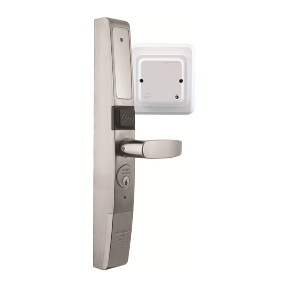
Aperio™ eForce
Narrow Stile Keyless Entry
Owner's Manual &
Installation Instructions
For Models
A100-3090H
Adams Rite Manufacturing Co.
Phone: 800-872-3267
www.adamsrite.com
®
A100
Advertisement
Table of Contents

Summary of Contents for Aperio eForce A100 A100-3090H
-
Page 1: Installation Instructions
® Aperio™ eForce A100 NORMAL OPERATION LOCK INDICATIONS Narrow Stile Keyless Entry NORMAL OPERATION HUB INDICATIONS Owner’s Manual & Installation Instructions For Models A100-3090H Adams Rite Manufacturing Co. 10027 S. 51st St. Suite 102 Phoenix, AZ 85044 Phone: 800-872-3267 Adams Rite Manufacturing Co. -
Page 2: Table Of Contents
Table of Contents Table of Contents TROUBLESHOOTING The eForce A100 LED is normally off until a credential is presented and then LED will momentarily turn green if credentials are valid. A red LED will show if credentials are not valid. Warning .................... -
Page 3: Warning
Replacement parts under the terms of the warranty must be fur- Aperio™ Aperio is a wireless lock technology for use with an access control sys- nished by the Adams Rite dealer or agency. tem. Aperio is developed by ASSA ABLOY, the global leader in door opening solutions. -
Page 4: System Overview
(F . 22). A100-3090H is connected to the access control system through the included wireless Aperio hub. The hub connects to the access control system with Wiegand wiring and signal wiring for REX, DPS, Tamper and Low Battery. ®... -
Page 5: Operational Description
Mount the A100 onto the mount- ing bracket and guide the spindle When a user presents a supported credential to the lock, the Aperio system is designed to send the credential wirelessly to the Aperio Hub. The Aperio into the Cam Plug. -
Page 6: Hub Location
STEP 6 REX/DPS CABLE INSTALLATION HUB LOCATION Choose the Hub location The hub should be mounted near the top of a wall, on the ceiling or above the ceiling to reduce potential for interference. For a stable and reliable radio link, it is recommended that the hub is located within fifty (50) feet of the lock. -
Page 7: Hub Wiring
MORTISE CYLINDER INSTALLATION HUB WIRING Using a Philips Head Screwdriver, The Aperio hub connects to the Access Control system via Wiegand remove the eight (8) #10-32 x 5/8” wiring. The hub requires 8-24VDC power (250mA). The hub has four ®... -
Page 8: Trim Installation Tools & Equipment
® TRIM INSTALLATION TOOLS & EQUIPMENT STEP 4 HANDING THE eForce ® The eForce is shipped in a non IMPORTANT NOTES: -handed neutral position with The A100-3090H-C/P-01, and A100-3090H-CK/PK-01 are designed exclu- the access cover off as shown. sively for latching hardware including: ... -
Page 9: Door Preparation
RIM Exit Device Application: A100-3090H for 8700/8800 STEP 1 DOOR PREPARATION On the back side of the exit device, re- move only the lower Phillips head screw, Select the stick-on template to match the appli- depending on hand of door, to free up the cation. -
Page 10: Spindle Preparation
STEP 2 SPINDLE PREPARATION STEP 3 CONFIGURE FOR LOCK SERIES (For 1-3/4” doors) Mortise Latch Application: A100-3090H for 4500/4900 (including 8300/8400 Exit Devices) For Adams Rite MS1850 Deadbolts, 4500/4900 Deadlatches, & 8000 Series Mortise Exit Devices: Configure the supplied cam plug to match the hand of door. Insert Snap-off spindle at fifth (5th) notch as shown in F .

Need help?
Do you have a question about the eForce A100 A100-3090H and is the answer not in the manual?
Questions and answers