Table of Contents
Advertisement
Quick Links
Download this manual
See also:
Operating Manual
TopPage
In the interests of user-safety (Required by safety regulation in some countries) the set should be restored to its
original condition and only parts identical to those specified should be used.
IMPORTANT SERVICE NOTES ............ . ............i
Precautions for using lead-free solder ... . .......... iii
[1]
SPECIFICATIONS ................................. . ....... 1-1
[1]
PARTS NAMES...................................... . ....... 2-1
[1]
REMOVING OF MAJOR PARTS ........... . ....... 3-1
[2]
IMPORTAMT SERVICE NOTICE........... . ....... 3-3
[3]
RY DEVICE............................................ . ....... 3-3
[1]
TROUBLESHOOTING TABLE (MAIN
PWB)...................................................... . ....... 4-1
[1]
BLOCK DIAGRAM ................................. . ....... 5-1
[1]
MAIN PWB ............................................. . ....... 6-1
[2]
LED/OPERATION PWB ......................... . ....... 6-5
Parts marked with "
" are important for maintaining the safety of the set. Be sure to replace these parts with specified ones for maintaining the
safety and performance of the set.
SERVICE MANUAL
BLU-RAY DISC/DVD PLAYER
MODEL
CONTENTS
[1]
GRAM............................................................7-1
[2]
GRAM............................................................7-2
[3]
GRAM............................................................7-3
[4]
GRAM............................................................7-4
[5]
GRAM............................................................7-5
[6]
LED CIRCUIT SCHEMATIC DIAGRAM ........7-6
[7]
GRAM............................................................7-7
No. S90K6BDHP90S/
BD-HP90S
This document has been published to be used for
after sales service only.
The contents are subject to change without notice.
BD-HP90S
Advertisement
Table of Contents

Subscribe to Our Youtube Channel
Related Manuals for Sharp BD-HP90S


Summary of Contents for Sharp BD-HP90S
-
Page 1: Table Of Contents
TopPage BD-HP90S SERVICE MANUAL No. S90K6BDHP90S/ BLU-RAY DISC/DVD PLAYER BD-HP90S MODEL In the interests of user-safety (Required by safety regulation in some countries) the set should be restored to its original condition and only parts identical to those specified should be used. -
Page 2: Safety Precaution
BD-HP90S BDHP90S SAFETY PRECAUTION Service Manual IMPORTANT SERVICE NOTES IMPORTANT SERVICE NOTES This Player is classified as a CLASS 1 LASER product. The CLASS 1 LASER PRODUCT label is located on the rear cover. This product contains a low power laser device. To ensure continued safety do not remove any cover or attempt to gain access to the inside of the product. - Page 3 BD-HP90S IMPORTANT SERVICE SAFETY PRECAUTION Service work should be performed only by qualified service technicians who are thoroughly familiar with all safety checks and the servicing guidelines which follow: WARNING Use an AC voltmeter having with 5000 ohm per volt, or higher, sen- sitivity or measure the AC voltage drop across the resistor.
-
Page 4: Precautions For Using Lead-Free Solder
BD-HP90S Precautions for using lead-free solder Employing lead-free solder • “All PWBs” of this model employs lead-free solder. The LF symbol indicates lead-free solder, and is attached on the PWBs and service manuals. The alphabetical character following LF shows the type of lead-free solder. -
Page 5: Chapter 1. Specifications
BD-HP90S CHAPTER 1. BDHP90S SPECIFICATIONS Service Manual [1] SPECIFICATIONS Specifications are subject to change without notice. General Power requirements DC 12V, 2A (with the supplied AC adapter) Power consumption (Normal) 17 W (with the supplied AC adapter at AC 230V, 50Hz) Power is automatically shut off if playback is stopped and you do not perform any operations for about 10 minutes. - Page 6 BD-HP90S Wireless LAN (Internal antenna) Frequency band Draft 802.11n Radio: 2.4GHz 802.11g Radio: 2.4GHz 802.11b Radio: 2.4GHz Europe - ETSI 2.412 – 2.472GHz (channel 1–13) Modulation DBPSK @ 1Mbps DQPSK@ 2Mbps CCK@ 5.5/11 Mbps BPSK@ 6/9 Mbps QPSK@ 12/18Mbps 16-QAM@ 24/36 Mbps...
-
Page 7: Chapter 2. Operation Manual
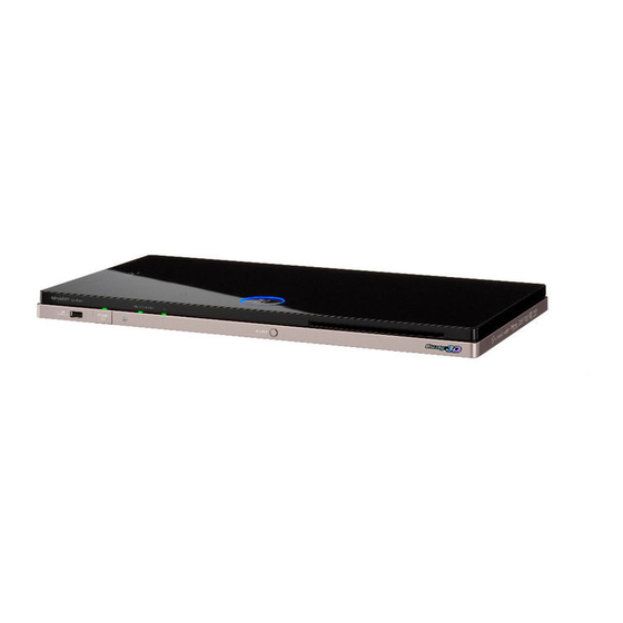
BD-HP90S CHAPTER 2. BDHP90S OPERATION MANUAL Service Manual [1] PARTS NAMES Major Components Main Unit (Front) NOTE When you insert or remove a USB memory device, be sure to turn the main power off. Remote control sensor “Top” POWER (On/Standby) indicator... -
Page 8: Remote Control Unit
BD-HP90S Major Components Remote Control Unit Power EJECT TOP MENU/TITLE LIST DISPLAY Cursor buttons ( / ), ENTER EXIT A (Red), B (Green), C (Yellow), D (Blue) AUDIO, SUBTITLE, ANGLE PinP REPEAT, OFF (for REPEAT) SKIP REPLAY (Lock) (See below.) -
Page 9: Chapter 3. Removing Of Major Parts
BD-HP90S CHAPTER 3. BDHP90S REMOVING OF MAJOR PARTS Service Manual [1] REMOVING OF MAJOR PARTS 3. Removing the Shield, Fan, Fix PWB and LED Holder 1. Removing the Stand Ass’y 1. Remove the 2 lock screws , 2 lock screws and detach the 1. - Page 10 BD-HP90S 5. Removing the BD DRIVE Unit 1. Disconnect the 2 FFCs 2. Remove the 2 lock screws and detach the BD DRIVE Unit 3. Remove the 2 lock screws and detach the Drive Angle-L from BD DRIVE Unit. Drive Angle-L BD DRIVE Unit 6.
-
Page 11: Importamt Service Notice
BD-HP90S [2] IMPORTAMT SERVICE NOTICE 1. Before replacing the main PWB, check up the software version. If its version is out of date, get it updated. 2. The IC7208, IC7806 and IC2504 have their own BD cryptography keys and programs already written on. For this reason, they cannot be individu- ally replaced with new ones. -
Page 12: Chapter 4. Troubleshooting Table
BD-HP90S CHAPTER 4. BDHP90S TROUBLESHOOTING TABLE Service Manual [1] TROUBLESHOOTING TABLE (MAIN PWB) Flowchart 1 Failure to power on the set. Is the power turned on? Is the Q9004-Base voltage (MAIN_P-con) at high level? Is the power turned off soon? Check Pin 85 of IC2504 (FuCon). - Page 13 BD-HP90S Flowchart 3 No audio from the coaxial digital terminal. Is there the digital audio signal output at TL7295? Check Pin 3 of J7202. Replace this parts as required. Check IC7208 and its peripheral circuits. Replace any of them as required.
- Page 14 BD-HP90S Flowchart 5 Failure to access the Internet through the Ethernet terminal. Does the system function even with a new cable in place? Cable defective. Does the signal come to Pins 1, 2, 3 and 6 of J7201? Check J7201 for poor contact. Replace as required.
-
Page 15: Chapter 5. Block Diagram Block Diagram
BD-HP90S BDHP90S CHAPTER 5. BLOCK DIAGRAM Service Manual [1] BLOCK DIAGRAM Blu-ray SYSTEM PROCESSOR TSOP 48pin IC7208 BGA 422balls BROADCOM FBGA 78balls FBGA 78balls FBGA 78balls FBGA 78balls 27MHz X7201 P7207 232C_RXD 232C_TXD F_TXD LED OUT F_RXD KEY IN COLD RST... -
Page 16: Chapter 6. Printed Wiring Board Assem- Blies Main Pwb
BD-HP90S BDHP90S CHAPTER 6. PRINTED WIRING BOARD ASSEMBLIES Service Manual [1] MAIN PWB MAIN UNIT Side-A 6 – 1... - Page 17 BD-HP90S MAIN UNIT Chip Parts Side-A 6 – 2...
- Page 18 BD-HP90S MAIN UNIT Side-B 6 – 3...
- Page 19 BD-HP90S MAIN UNIT Chip Parts Side-B 6 – 4...
-
Page 20: Led/Operation Pwb
BD-HP90S [2] LED/OPERATION PWB LED UNIT Side-A LED UNIT Side-B LUG1401 SC1404 RMC1401 C1402 R1406 RMC1401 R1407 FF560WJ Sn-Ag-Cu R1408 KF560TE SC1403 SC1403 OPERATION UNIT Side-A (GREEN) D1203 Q1204 LUG1201 D1202 Q1203 SC1201 EJECT J1201 D1201 D1204 FF561WJ KF561TE R1204... -
Page 21: Chapter 7. Schematic Diagrams Main (1) Circuit Schematic Dia- Gram
BD-HP90S BDHP90S CHAPTER 7. SCHEMATIC DIAGRAMS Service Manual [1] MAIN (1) CIRCUIT SCHEMATIC DIAGRAM L7205 10uH J7202 GP1F55TKVY Q7201 BCM7633 R7247 R7257 RT1N241C TL7295 Q7202 2SA1530AR TL7296 R7244 C7252 100u C7274 6.3V 0.1u TL7297 TO POWER [Sht 005] AT_5V AT_5V MAIN_P-CON D_3.3V... -
Page 22: Main (2) Circuit Schematic Diagram
BD-HP90S [2] MAIN (2) CIRCUIT SCHEMATIC DIAGRAM D_1.5V D_1.5V D_GND C7862 D_3.3V D_3.3V R7878 NAND_CLE (PWB) R7875 R7879 1.5K NAND_RE R7876 R7880 1.5K (PWB) NAND_WE1 R7877 R7881 1.5K (PWB) FL7810 FL7820 (PWB) R7805 NA119WJ NA119WJ NAND_WE0 R7882 R7807 C7861 NAND_ALE 220u 4.7K... -
Page 23: Main (3) Circuit Schematic Diagram
BD-HP90S [3] MAIN (3) CIRCUIT SCHEMATIC DIAGRAM D_3.3V AT_12V R2591 R2593 6.8K 3.3K R2508 R2513 F_AT_5V R/C_SELECT TL2516 (PWB) SA033WJQZ TO BCM7632 SUB_P-CON S2501 [Sht 001] DRIVE_P-CON HDMI_SDA HDMI_SDA MAIN_P-CON HDMI_SCL HDMI_SCL SUB_SHORT_DET SUB_SHORT_DET R2594 R2592 HPD_IN HPD_IN D_GND FR_CECIN... -
Page 24: Main (4) Circuit Schematic Diagram
BD-HP90S [4] MAIN (4) CIRCUIT SCHEMATIC DIAGRAM TO POWER [Sht 005] DRIVE_12V L3001 4.7uH F3001 DRIVE_5V 0.5A C3004 C3005 D_3.3V 0.1u QFS-LA058WJZZY D_3.3V D_GND SC3003 WA868WJQ1 TL3067 OFE_GP_PB0 GNDM TL3068 C3021 GNDM IC3003 TL3069 SC3001 NA480WJQZ @pinCo TL3070 AZ1117HA @pinCo... -
Page 25: Main (5) Circuit Schematic Diagram
BD-HP90S [5] MAIN (5) CIRCUIT SCHEMATIC DIAGRAM AND SHADED COMPONENTS=SAFETY RELATED PARTS TO F-uCOM DRIVE_12V [Sht 003] AT_12V F_AT_5V D9015 D9014 TL9004 D_GND DA1010 DA1010 DRIVE_5V LOW_POWER_CTL TL9020 5.2V DC-DC 5.216V Q9012 D9012 C9035 DA1010 C9031 C9032 RTQ035P02 R9041 C9039... -
Page 26: Led Circuit Schematic Diagram
BD-HP90S [6] LED CIRCUIT SCHEMATIC DIAGRAM RMC1401 RRMCUA087WJQZ 11mA SC1404 SC1403 N0534FJQ1 TL1401 TL1415 Q1401 KEY_STBY 2SC4081 TL1402 TL1416 D_3.3V R1407 TL1403 TL1417 LUG1401 HA006WJ TL1404 TL1418 LED_PON TL1405 TL1419 R/C_OPE R/C_OPE R/C OPE LED_STBY TL1406 TL1420 LED_PLAY AQUOS_PURE_LED TL1407... -
Page 27: Operation Circuit Schematic Diagram
BD-HP90S [7] OPERATION CIRCUIT SCHEMATIC DIAGRAM STBY S1201 KA037WJ RMC1201 UA089WJQZ LUG1201 PA210WJQZ STAND-BY P-ON AQUOS PURE SC1201 C1202 6.3V TL1201 KEY_STBY TL1202 EJECT TL1203 Q1201 Q1202 Q1203 Q1204 S1251 KA037WJ RT1N141M RT1N141M RT1N141M RT1N141M TL1204 LED_PON LED_PON TL1205 LED_STBY... - Page 28 BD-HP90S - MEMO - 7 – 8...
-
Page 29: Parts Guide
BD-HP90S PartsGuide PARTS GUIDE No. S90K6BDHP90S/ BLU-RAY DISC/DVD PLAYER BD-HP90S MODEL CONTENTS PRINTED WIRING BOARD CABINET PARTS ASSEMBLIES SUPPLIED ACCESSORIES DSETV0218TEVZ (MAIN Unit) PACKING PARTS (NOT DUNTKF560TE6A (LED Unit) REPLACEMENT ITEM) DUNTKF561TE6A (OPERATION INDEX Unit) Parts marked with " " are important for maintaining the safety of the set. Be sure to replace these parts with specified ones for maintaining the safety and performance of the set. - Page 30 BD-HP90S PRICE PARTS CODE PART DESCRIPTION RANK MARK DELIVERY [1] PRINTED WIRING BOARD ASSEMBLIES MAIN Unit DSETV0218TEVZ LED Unit DUNTKF560TE6A OPERATION Unit DUNTKF561TE6A BD Drive Unit RUNTDA045WJQZ [2] DSETV0218TEVZ (MAIN Unit) C2503 Capacitor 100 6.3V Electrolytic VCEAPF0JW107MY C2504 Capacitor 0.047 10V Ceramic...
- Page 31 BD-HP90S PRICE PARTS CODE PART DESCRIPTION RANK MARK DELIVERY [2] DSETV0218TEVZ (MAIN Unit) C7227 Capacitor 0.1 10V Ceramic VCKYCZ1AB104KY C7228 Capacitor 0.1 10V Ceramic VCKYCZ1AB104KY C7229 Capacitor 10 10V Ceramic RC-KZA176WJZZY C7230 Capacitor 0.01 25V Ceramic VCKYCZ1EB103KY C7231 Capacitor 0.1 10V Ceramic...
- Page 32 BD-HP90S PRICE PARTS CODE PART DESCRIPTION RANK MARK DELIVERY [2] DSETV0218TEVZ (MAIN Unit) C7833 Capacitor 0.1 10V Ceramic VCKYCZ1AB104KY C7834 Capacitor 0.1 10V Ceramic VCKYCZ1AB104KY C7835 Capacitor 0.1 10V Ceramic VCKYCZ1AB104KY C7836 Capacitor 0.1 10V Ceramic VCKYCZ1AB104KY C7837 Capacitor 0.1 10V Ceramic...
- Page 33 BD-HP90S PRICE PARTS CODE PART DESCRIPTION RANK MARK DELIVERY [2] DSETV0218TEVZ (MAIN Unit) FB9002 Ferrite Core RBLN-A018WJZZY FB9003 Ferrite Core RBLN-A018WJZZY FB9004 Ferrite Core RBLN-A018WJZZY FB9005 Ferrite Core RBLN-A018WJZZY FB9006 Ferrite Core RBLN-A018WJZZY FB9007 RBLN-A018WJZZY Ferrite Core FB9008 Ferrite Core...
- Page 34 BD-HP90S PRICE PARTS CODE PART DESCRIPTION RANK MARK DELIVERY [2] DSETV0218TEVZ (MAIN Unit) Q9004 Transistor RT1N441C-T112-1 VSRT1N441C/-1Y Q9005 Transistor 2SC3928A-T112-1R VS2SC3928AR-1Y Q9008 Transistor RSS040P03TB VSRSS040P03-1Y Q9009 Transistor RT1N241C-T112-1 VSRT1N241C/-1Y Q9010 Transistor RT1N241C-T112-1 VSRT1N241C/-1Y Q9011 VSRT1N241C/-1Y Transistor RT1N241C-T112-1 Q9012 Transistor RTQ035P02TR...
- Page 35 BD-HP90S PRICE PARTS CODE PART DESCRIPTION RANK MARK DELIVERY [2] DSETV0218TEVZ (MAIN Unit) R3105 Resistor 0 1/16W Metal Oxide VRS-CZ1JF000JY R3108 Resistor 5.6k 1/16W Metal Oxide VRS-CZ1JF562JY R3109 Resistor 5.6k 1/16W Metal Oxide VRS-CZ1JF562JY R3110 Resistor 5.6k 1/16W Metal Oxide...
- Page 36 BD-HP90S PRICE PARTS CODE PART DESCRIPTION RANK MARK DELIVERY [2] DSETV0218TEVZ (MAIN Unit) R7847 Resistor 47 1/16W Metal Oxide VRS-CZ1JF470JY R7848 Resistor 47 1/16W Metal Oxide VRS-CZ1JF470JY R7849 Resistor 47 1/16W Metal Oxide VRS-CZ1JF470JY R7851 Resistor 10k 1/16W Metal Oxide...
- Page 37 BD-HP90S PRICE PARTS CODE PART DESCRIPTION RANK MARK DELIVERY [2] DSETV0218TEVZ (MAIN Unit) SC3001 Socket QSOCNA480WJQZY SC3003 Connector QCNCWA868WJQ1Y SC7201 Socket QSOCZA224WJPZQ SG7204 Capacitor 10p 50V Ceramic VCCCCZ1HH100DY SG7206 Capacitor 10p 50V Ceramic VCCCCZ1HH100DY SG7213 RH-VXA187WJQZY Discharge Gap EZAEG2A50AX SG7214...
- Page 38 BD-HP90S [5] CABINET PARTS MAIN Unit LED Unit BD DRIVE Unit OPERATION Unit 28-2 28-1...
- Page 39 BD-HP90S PRICE PARTS CODE PART DESCRIPTION RANK MARK DELIVERY [5] CABINET PARTS Top Cabinet Ass'y CCABAC624TEV1 Bottom Cabinet Ass'y CCABBB868TEV1 Terminal Cover Ass'y CCOVAD828TEV1 Chassis GBDYUA417WJFW Drive Angle-L LANGFA763WJFW Shield LANGFA773WJFW DC Holder LHLDZB646WJZZ Screw (M3x2.8) LX-BZA148WJF7 Screw (M3x6), x9...
- Page 40 BD-HP90S [7] PACKING PARTS (NOT REPLACEMENT ITEM) PRICE PARTS CODE PART DESCRIPTION RANK MARK DELIVERY [7] PACKING PARTS (NOT REPLACEMENT ITEM) Packing Case SPAKCF888WJZZ Mirror Mat SPAKPB513WJZZ SPAKXD056WJZZ Bottom Add SPAKXD057WJZZ Top Add Polyethylene Bag SSAKA0005PEZZ Serial No. Label TLABZC447WJZZ...
- Page 41 BD-HP90S...
- Page 42 BD-HP90S © COPYRIGHT 2010 BY SHARP CORPORATION ALL RIGHTS RESERVED. No part of this publication may be reproduced, stored in a retrieval system, or transmitted in any form or by any means, electronic, mechanical, photocopying, recording, or otherwise, without prior written permission of the publisher.
Need help?
Do you have a question about the BD-HP90S and is the answer not in the manual?
Questions and answers