Table of Contents
Advertisement
Quick Links
SERVICE MANUAL
Read this manual carefully, especially precaution on microwave energy, and follow the procedure strictly.
Careless servicing and testing may expose yourself to the microwave energy leakage.
PRECAUTIONS TO BE OBSERVED BEFORE AND DURING SERVICING TO AVOID POSSIBLE EXPOSURE TO
EXCESSIVE MICROWAVE ENERGY
(a) Do not operate or allow the oven to be operated with the door open.
(b) Make the following safety checks on all ovens to be serviced before activating the magnetron or other
microwave source, and make repairs as necessary :
(1) Interlock operation, (2) proper door closing, (3) seal and sealing surfaces (arcing, wear, and other damage),
(4) damage to or loosening of hinges and latches, (5) evidence of dropping or abuse.
(c) Before turning on microwave power for any service test or inspection within the microwave generating
compartments, check the magnetron, wave guide or transmission line, and cavity for proper alignment, integrity,
and connections.
(d) Any defective or misadjusted components in the interlock, monitor, door seal, and microwave generation and
transmission systems shall be repaired, replaced, or adjusted by procedures described in this manual before
the oven is released to the owner.
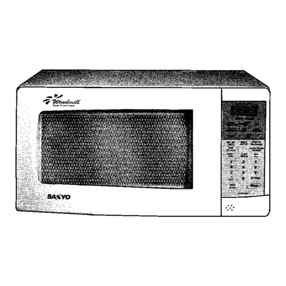
Microwave Oven EM-V3410WW
Foreword
PRECAUTIONS
File No :
EM-V3410WS
Model No : -
Product Code No : -
EM-V3410WW
EM-V3410WS
REFERENCE NO. SM-860326
(AUSTRALIA)
437 520 15
437 520 16
Advertisement
Table of Contents

Related Manuals for Sanyo EM-V3410WW


Summary of Contents for Sanyo EM-V3410WW
- Page 1 File No : SERVICE MANUAL Microwave Oven EM-V3410WW (AUSTRALIA) EM-V3410WS Model No : - Product Code No : - EM-V3410WW 437 520 15 EM-V3410WS 437 520 16 Foreword Read this manual carefully, especially precaution on microwave energy, and follow the procedure strictly.
-
Page 2: Adjustment Procedures
- TABLE OF CONTENTS - Adjustment Procedures .......... Test Procedures and Troubleshooting ....4 ~ 10 Specifications ............Disassembly Instructions ........ 11 ~ 14 Power Output Measurement ........Exploded View and Parts List ......15 ~ 20 Precautions and Repair Service Tips ......Overall Circuit Diagram ........ -
Page 3: Specifications
4. PRECAUTIONS AND REPAIR SERVICE TIPS 2. SPECIFICATIONS PRELIMINARY Rated Power Consumption .. 1500W. A. SINCE NEARLY 4,000 VOLTS EXISTS IN SOME CIR- Microwave Output ..... 1000W. CUITS OF THIS MICROWAVE OVEN, REPAIRS SHOULD Frequency ......2,450MHz±50MHz. BE CARRIED OUT WITH GREAT CARE. Power Supply .... -
Page 4: Circuit Diagram
5. CIRCUIT DIAGRAM Figure 2 • • • • • - 3 -... -
Page 5: Test Procedures And Troubleshooting
6. TEST PROCEDURES AND TROUBLESHOOTING Filament Windings CAUTION - DISCONNECT THE POWER SUPPLY CORD FROM THE WALL OUTLET WHENEVER REMOVING THE Secondary CABINET FROM THE UNIT. PROCEED WITH THE Windings TESTS ONLY AFTER DISCHARGING THE HIGH VOLTAGE CAPACITOR AND REMOVING THE LEAD WIRES FROM THE PRIMARY WINDING OF THE HIGH VOLTAGE TRANSFORMER. -
Page 6: High-Voltage Diode
COMPONENT CHECKOUT PROCEDURE RESULT Measure the resistance : Across two terminals Normal reading : HIGH-VOLTAGE with an Ohm-Meter on highest scale. Momentarily indicates several ohms, CAPACITOR and gradually returns to 10 Meg-Ohms. including Abnormal reading : BLEEDER Indicates continuity or 10 Meg-Ohms RESISTOR Ohm-Meter from the beginning. - Page 7 COMPONENT CHECKOUT PROCEDURE RESULT When When not Measure the resistance between terminals of touched touched Resistance FPC connector after removing it from S101. value Less than More than (Figure 10). 1K Ohms 1 MEG Ohms NOTE TOUCH KEY - When reconnecting the FPC connector, make When checking “START”...
- Page 8 - 7 -...
- Page 9 - 8 -...
- Page 10 - 9 -...
- Page 11 - 10 -...
- Page 12 7. DISASSEMBLY INSTRUCTIONS • OVEN MUST BE DISCONNECTED FROM ELECTRICAL B. REMOVING PRIMARY INTERLOCK SWITCH OUTLET WHEN MAKING REPLACEMENTS, REPAIRS, AND INTERLOCK MONITOR SWITCH ADJUSTMENTS AND CONTINUITY CHECKS BEFORE (Figure 11-b) PROCEEDING WITH ANY REPAIR WORK. AFTER DISCONNECTING, WAIT AT LEAST 1 MINUTE, UNTIL THE CAPACITOR IN THE HIGH-VOLTAGE AREA (1) Disconnect all wire leads from Primary Interlock and HAS FULLY DISCHARGED.
-
Page 13: Removing Magnetron
C. REMOVING BLOWER MOTOR (Figures 12 (Top View) and 13). Duct (mag. exhaust) Blower Base (1) Remove screw securing the stay. (2) Disconnect all lead wires from the Blower Motor and H.V. Capacitor. Thermal Protector Screw (3) Remove 2 screws securing the Blower Base and disengage 3 hooks from the Rear Plate of Cavity (Figure 13). - Page 14 REMOVING FUSE Remove the 8A Fuse with a screwdriver. NOTE When replacing the 8A Fuse, be sure to use an exact repair part. Control Base If the 8A Fuse blows immediately, check the Primary Interlock Switch, the Relay 2 (on the Control Circuit Board) and the Interlock Monitor Switch according to, “CHECKOUT PROCEDURE FOR SWITCHES”...
-
Page 15: Removing Door
J. REMOVING CAVITY COVER H. REMOVING DOOR (Figure 17) (1) Remove 2 hex nuts securing the upper hinge. (1) To detach the Cavity Cover from light side of the Oven (2) Tilt the top of the door toward you. Cavity. Insert a thin flat-screwdriver between Cavity (3) Lift up the door to remove it. - Page 16 8. EXPLODED VIEW AND PARTS LIST CAVITY PARTS ALL SERVICE ON MICROWAVE OVENS SHOULD BE PERFORMED BY A QUALIFIED TECHNICIAN USING APPROVED TESTING EQUIPMENT. CUSTOMERS SHOULD NOT ATTEMPT TO REPLACE PARTS IDENTIFIED BY A TRIPLE ASTERISK (***). Part No. Description Q’ty Part No.
- Page 17 SWITCHES AND MICROWAVE PARTS ALL SERVICE ON MICROWAVE OVENS SHOULD BE PERFORMED BY A QUALIFIED TECHNICIAN USING APPROVED TESTING EQUIPMENT. CUSTOMERS SHOULD NOT ATTEMPT TO REPLACE PARTS IDENTIFIED BY A TRIPLE ASTERISK (***). Part No. Description Q’ty Part No. Description Q’ty 411 082 5201 SCR TPG TRS 4 x 10 Z1...
-
Page 18: Door Parts
DOOR PARTS ALL SERVICE ON MICROWAVE OVENS SHOULD BE PERFORMED BY A QUALIFIED TECHNICIAN USING APPROVED TESTING EQUIPMENT. CUSTOMERS SHOULD NOT ATTEMPT TO REPLACE PARTS IDENTIFIED BY A TRIPLE ASTERISK (***). Part No. Description Q’ty Part No Description Q’ty 617 243 3455 Door Cover*** (V3410WW) 617 228 6242 Choke Dielectric***... -
Page 19: Control Panel Parts
CONTROL PANEL PARTS ALL SERVICE ON MICROWAVE OVENS SHOULD BE PERFORMED BY A QUALIFIED TECHNICIAN USING APPROVED TESTING EQUIPMENT. CUSTOMERS SHOULD NOT ATTEMPT TO REPLACE PARTS IDENTIFIED BY A TRIPLE ASTERISK (***). Part No. Description Q’ty Part No. Description Q’ty 617 228 0752 Control Base*** 617 239 7924... -
Page 20: Control Circuit Board
CONTROL CIRCUIT BOARD (Part No. 617 237 4116) 4 710 0 - 19 -... - Page 21 CONTROL CIRCUIT BOARD (Part No. 617 237 4116) Key No. Order Part No. Description Q’ty Key No. Order Part No. Description Q’ty RESISTORS. INTEGRATED CIRCUIT R111, 118 401 012 5609 Carbon, 1K ohms IC11 409 493 2100 IC LM8905-323FP. +-5%, 1/4W. TRANSISTORS R26, 108, 401 012 6903 Carbon, 10K ohms...
-
Page 22: Overall Circuit Diagram
9. OVERALL CIRCUIT DIAGRAM - 21 -... - Page 24 SANYO Electric Co., Ltd. FEBRUARY 2001. Printed in Singapore Osaka, Japan.
Need help?
Do you have a question about the EM-V3410WW and is the answer not in the manual?
Questions and answers