Table of Contents
Advertisement
Advertisement
Table of Contents

Summary of Contents for Complett HAND-STITCH 886
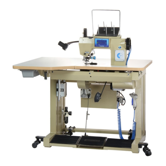
- Page 1 MOD. “HAND-STITCH” Machine for decorative sewing USER’S AND MAINTENANCE MANUAL...
- Page 3 COMPLETT s.r.l. shall not be held civilly or criminally liable for an accidents which are the result of a failure, even partial, to comply with even one of the instructions and warning container in this manual.
- Page 4 SAFETY REGULATIONS Failure to comply with these safety regulations may cause injury to individuals or damage to the machine The machine must be installed by specifically trained specialized personnel, after having carefully read the instructions. The machines have been designed and built to meet safety requirements for operation in dry and accurately cleaned environments and for sewing dry fabric.
-
Page 5: Table Of Contents
INDEX SEWING MACHINE INSTALLATION ADJUSTING THE SLOW STITCH DEVICE Bench and lamp assembly Assembly and timing Motor voltage Test runs 17 ADJUSTING THE SYNCHRONISED SLOW STITCH DEVICE DESCRIPTIVE CHART OF WORK CYCLES Description Description Adjustement NEEDLE TABLE ADJUSTING TENSION STARTING Needle category Position Needle size... -
Page 6: Sewing Machine Installation
1 – SEWING MACHINE INSTALLATION BENCH AND LAMP ASSEMBLY (Fig. 1) Secure the table (1) to the bench using the holes set up for securing the hinges, fit the drawer holder support (2), fit the multiple bobbin holder (3) in the lower part of the head, so that the chromed rod for threading the thread is in a vertical position above the head, fit the front work surface (4), complete with... -
Page 7: Descriptive Chart Of Work Cycles
2 – DESCRIPTIVE CHART OF WORK CYCLES DESCRIPTION The formation of the stitch occurs in two work cycles. cycle: Formation of the stitch on the upper part of the fabric. The 1 cycle starts with the threaded needle which descends from the P.M.S. -
Page 8: Needle Table
3 - NEEDLE TABLE Use SCHMETZ type 780 C.C03.SPI.DH needles only. For a better use of needles see the attached tables. COMPLETT NEEDLE CATEGORY Type Round tip needle 780 C 780 C03 Round tip needle with decreased eye 780 SPI Very sharp round tip needle... -
Page 9: Adjusting Needle And Point
4 – ADJUSTING NEEDLE AND POINT Needle replacement (Fig. 5) Loosen clamp 26 and remove the needle by pulling it up. Select the needle size with the corresponding needle guide from those indicated in the table. Insert the needle with the flat part of the shank towards the left in the clamp 26 and needle guide hole 17. -
Page 10: Adjusting Needle Bar Height
5 – ADJUSTING NEEDLE BAR HEIGHT Turn the hand wheel until the needle bar is at its P.M.S. Loosen the guide clamp screw (20). Adjust its height so that the distance between the needle tip and needle plate measure with a calliper (29) Fig. 9 is in compliance with the timing table (e.g. -
Page 11: Adjusting The Upper Hook
6 – ADJUSTING THE UPPER HOOK Assembly and timing: Fit the upper hook (46) by positioning its tip at a height of approximately 0.3 mm over the needle bar height, from the needle plate plane. The hook tip must have an inclination compared to the needle of approximately 5°, to avoid breaking the needle in the return stroke Fig.11. -
Page 12: Adjusting The Needle Guard
7 – ADJUSTING THE NEEDLE GUARD Positioning: Make sure there is no axial play in the thread movement lever unit (42) Fig. 15 To eliminate any play push the internal pin (43) towards the base of the machine so that the unit always remains free to rotate on the pin. -
Page 13: Adjusting The Thread Movement Hook
8 – ADJUSTING THE THREAD MOVEMENT HOOK Positioning and timing: The thread movement hook (37) must be installed so that its tip projects forward 0.3 mm from its leg. Fig. 17. Turn the hand wheel to bring the thread movement hook to the end of its stroke, then adjust the height so that there is 0.3 mm between the lower unloaded part of the plate and the highest point of the thread movement hook. -
Page 14: Adjusting The Thread Loader
9 – ADJUSTING THE THREAD LOADER Positioning and timing: The thread loader (77) is used to load the thread on the needle, with the needle bar rising from the P.M.I. of the second cycle. The rear part (A) of the thread loader, in its position closest to the needle, needs to barely touch it without bending it at a distance of 0.1 mm. -
Page 15: Adjusting The Rotating Crochet
10 – ADJUSTING THE ROTATING CROCHET Timing: Remove the thread loader wheel (52) and remove the rotating hook (47) from the thread loader wheel. Remove the pin with the pulley (54) being careful to not lose the pulley and clean everything accurately. -
Page 16: Adjusting The Thread Lifter
11 – ADJUSTING THE THREAD LIFTER Positioning and timing: To distinguish between the two thread lifters we will call them front (72) the nearest to the operator and rear (73) the nearest to the needle. The front thread lifter needs to be 3.5-4.5 mm from the edge of the thread loader wheel and the rear one 5.5-8 mm. Fig. -
Page 17: Adjusting The Tensioning Unit
12 – ADJUSTING THE TENSIONING UNIT Adjustments: Remove the thread loader wheel. Disassemble the tensioning unit (58) remove the nut (59) of the tie-rod with spherical jointed head and the two screws which secure the unit. Fig. 31-32. Adjust the spring of the thread holder (62-63) levers using the ring nut (64) after having loosened the screw (65). -
Page 18: Electromechanical Resetting Of The
13 – ELECTROMECHANICAL RESETTING OF THE FEEDER Adjustements: - Loosen the screw 1 on the driver pulley Fig. 40 Press the 2 key on the display, enter the menu "stitch length" and set both values of upper limit and the lower point of " 0 ". If they are stored over a sequence of points, press the key 31 and set "... -
Page 19: Adjusting The Lower Feeder
14 – ADJUSTING THE LOWER FEEDER Positioning and timing: 1) Exactly centre the plate needle hole (28) with the needle making sure the plate is perpendicular Fig. 38. 2) Set the upper and lower stitch length to the maximum on the sewing machine display. -
Page 20: Adjusting The Upper Feeder And
15 – ADJUSTING THE UPPER FEEDER AND PRESSER FOOT Assembly and timing: Insert the driven foot (107) in the support (112), in a machine cycle where the jaw is under the needle plate. Fig. 42. Use the knee pedal to obtain a distance of round 0.3 mm between the guide lever (116) and presser foot feeder (108). Align the driven foot with the jaw. -
Page 21: Adjusting The Slow Stitch Device
16 – ADJUSTING THE SLOW STITCH DEVICE Assembly and timing: In P.M.I. needle position check the distance show in fig. 45 between part 127 and casting. Turn the wheel by bringing the machineto the position where the upper hook 46 fig. 28 start its stroke towards the needle in the 1st cycle. -
Page 22: Adjusting The Synchronised
17 – INSTRUCTIONS FOR ADJUSTING THE SYNCHRONISED SLOW STITCH KIT Description: The P.L.S. device is used to adjust the upper stitch tension in two times. If we use a short – long stitch at times we find two different thread tensions when the stitch inverter is enabled. The longer stitch is slower than the short stitch. -
Page 23: Adjusting Tension Starting
18 – ADJUSTING TENSION STARTING Positioning: The thread brake tension unit (135) is used to hold the thread during the first stitches, before it is cut. The tension must only start when the knee pedal is used. Adjustment of the tension unit is obtained by adjusting the height of cam (136) installed inside the arm on the foot lifting connection (137) or by moving the unit (135) along its axis, after having loosened the locking screw (138). -
Page 24: Maintenance And Lubrication
19 – MAINTENANCE AND LUBRICATION The lubrication and cleaning of the machine must be effected periodically at least once a month. Remove machine operation, except for the ball bearings and various areas where the thread passes. The cam must be lubricated with special grease for gears, for all the other moving parts use dense seed oil for industrial sewing machine type TERESSO 32 E/50°... - Page 25 LUBRICATION LOWER...
- Page 26 LUBRICATION LOWER...
- Page 27 Stitch length: long stitch max 7,0 mm. short stitch minimum 0,8 mm. Electronic conveying Stitch attachment Programmable sewing Synchronised slow stitch Complett dedicated electrinics Thread section: maximum length 80 cm. Air pressure: 5 atmospheres. Lamp: Led Dimension: support 60x90 table 94,5 x 120 work surface height cm. 83.
- Page 28 Via Treviglio, 15 24053 Brignano Gera d’Adda - ITALIA INTERNET: http://www.complett.it – MAIL: complett.srl@complett.it...
Need help?
Do you have a question about the HAND-STITCH 886 and is the answer not in the manual?
Questions and answers