Table of Contents
Advertisement
Quick Links
Advertisement
Table of Contents

Subscribe to Our Youtube Channel
Summary of Contents for Continuum Caliburn
- Page 1 Caliburn Turntable Installation Manual REVISION ‘D’...
- Page 2 Caliburn in as-new condition for many years to come. If you have any questions in reference to any part of your Caliburn at any time in the future, please feel free to contact your nearest Continuum Consultant for assistance.
-
Page 3: Table Of Contents
Continuum Audio Laboratories – Caliburn Installation Manual TABLE OF CONTENTS IMPORTANT INFORMATION AND NOTES...................5 WHO SHOULD READ THIS MANUAL ...................5 HOW TO READ THIS MANUAL ......................5 Standard Symbols and Safety Notifications ..................5 ..........................6 AFETY RECAUTIONS CALIBURN SYSTEM COMPONENTS.....................7 CALIBURN TURNTABLE.......................7 CALIBURN CONTROL UNIT ......................7... - Page 4 Continuum Audio Laboratories – Caliburn Installation Manual MOTOR............................45 MOTOR BELT REPLACEMENT....................45 FAULTS & TROUBLE SHOOTING ....................46 SPECIFICATIONS..........................47 CALIBURN’S DESIGN HISTORY ....................48 APPENDIX 1 – R .................50 ECOMMENDED ATTERY ETAILS Written By: MDO Approved By: PLO Revision D – 01-JUN-08 Page 4 of 52...
-
Page 5: Important Information And Notes
CAUTION (CAUTION without the exclamation mark) Ignoring the instructions under this symbol when using the Caliburn may lead to damage to the device or hardware options. Written By: MDO Approved By: PLO Revision D –... -
Page 6: Safety Precautions
AC power cord must be changed only at a qualified service shop. Fitting The components in the Caliburn are made to close tolerances with sliding fits on most bearing surfaces. Never over tighten any of the provided fasteners components for assembling the platter. -
Page 7: Caliburn System Components
The Caliburn consists of separate subsystems that combine to create a most sophisicated analogue playback system. CALIBURN TURNTABLE The Caliburn turntable is a precisely engineered piece of equipment designed to be a low noise foundation for the record to sit, allowing the stylus to extract the maximum information from the record’s groove. -
Page 8: Revision D – 01-Jun
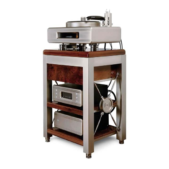
Continuum Audio Laboratories – Caliburn Installation Manual Castellon Stand Written By: MDO Approved By: PLO Revision D – 01-JUN-08 Page 8 of 52... -
Page 9: Overview Of Basic Installation Steps
Continuum Audio Laboratories – Caliburn Installation Manual Overview of Basic Installation Steps Perform the steps below to install the Castellon. Details are contained in this manual. Read the User Manual (this manual) ↓ Unpack and Check the contents of the packaging ↓... -
Page 10: Packaging
The packaging is designed to handle the majority of expected shipping conditions but there may be instances where events beyond Continuum Audio Laboratories control have occurred in shipping. To avoid complications with warranty claims we recommend you contact your dealer for assistance in evaluating the packaging prior to unpacking and installation. -
Page 11: Castellon Overview
The Castellon is a very specialised design incorporating the latest technology in vibration control. The stand contains a negative stiffness mechanism which works in harmony with the Caliburn to produce unequalled sonic results. This spring mass damper system are hidden beneath the attractive exterior. -
Page 12: Castellon Layers
Continuum Audio Laboratories – Caliburn Installation Manual CASTELLON LAYERS Once you have installed the stand in the correct location you need to insert the various shelf components, ceramic levitating shelves, ballast metal sheets and damping material sheets. Custom Finish Top... -
Page 13: Install Lower Ceramic Shelf
Continuum Audio Laboratories – Caliburn Installation Manual INSTALL LOWER CERAMIC SHELF Carefully lower the Bottom Ceramic Levitating Shelf into the recess in the top of the stand. Secure at each corner with the supplied M6 x 20MM Socket Head Cap Screws. - Page 14 Continuum Audio Laboratories – Caliburn Installation Manual Secure the flat plate washers and wingnuts as shown. Install the Pneumatic Horizontal Stabilizer (do not inflate at this stage) by wrapping it around the outer edge of the UPPER Ceramic Shelf. Ensure the inflation valve is centered at the rear of the Castellon Stand inline with the cutout.
- Page 15 Continuum Audio Laboratories – Caliburn Installation Manual Install the Safety Bolt and tighten this until it is flush with the top surface. Written By: MDO Approved By: PLO Revision D – 01-JUN-08 Page 15 of 52...
-
Page 16: Installing The Damping & Ballast Layers
Continuum Audio Laboratories – Caliburn Installation Manual INSTALLING THE DAMPING & BALLAST LAYERS Install the alternating layers of damping material and ballast metal sheets in the following order: After Ceramic UPPER Shelf Secured into stand 1 x 3MM Damping Sheet (EPDM Rubber) 1 x 3MM Ballast Metal Sheet . - Page 17 Remove the M10 Allthread Guide Bolts to allow clear room for the Drawer Mechanism: YOU MUST ENSURE SAFETY BOLT REMAINS INSTALLED. THIS IS TO PREVENT THE LEVITATION SYSTEM FROM RELEASING INADVERTENTLY SHOULD SOMEONE REMOVE THE CALIBURN TURNTABLE OFF THE STAND WITHOUT FOLLOWING PROPER INSTRUCTIONS INSTALL THE DRAWER MECHANISM Written By: MDO Approved By: PLO Revision D –...
-
Page 18: Control Box
Continuum Audio Laboratories – Caliburn Installation Manual CONTROL BOX THE CONTROL BOX IS USED TO SET SPEEDS, TURN VACUUM AND LOGO LIGHT ON/OFF. We recommend this is installed in the middle shelf of the Castellon VACUUM BOX THE VACUUM BOX IS USED TO DELIVER NEGATIVE PRESSURE FOR VACUUM HOLDDOWN. -
Page 19: Inflation Of The Horizontal Stabiliser
Continuum Audio Laboratories – Caliburn Installation Manual INFLATION OF THE HORIZONTAL STABILISER Once the Caliburn has been fully installed on to the Castellon a settling procedure is required to centralize and level the levitating ceramic shelves. Use the supplied manual inflation pump to add about 5-6PSI of low pressure to provide a “rolling”... -
Page 20: Caliburn Turntable
Continuum Audio Laboratories – Caliburn Installation Manual Caliburn Turntable Written By: MDO Approved By: PLO Revision D – 01-JUN-08 Page 20 of 52... -
Page 21: Overview Of Basic Installation Steps
Continuum Audio Laboratories – Caliburn Installation Manual OVERVIEW OF BASIC INSTALLATION STEPS Perform the steps below to install the Caliburn. Details are contained in this manual. Read the Caliburn Installation Manual (this manual) ↓ Unpack and Check the contents of the packaging ↓... -
Page 22: Packaging Contents
Continuum Audio Laboratories – Caliburn Installation Manual PACKAGING CONTENTS THERE ARE 6 MAIN COMPONENTS WHICH COMPRISE THE CALIBURN TURNTABLE SYSTEM Roadcase 1 – Platter, Chassis, Bearing, Motor, Top Plate and assembly parts. Roadcase 2 – Castellon Stand Assembly and Shelving Box 3 –... -
Page 23: Chassis, Bearing, Armboard Assembly
Continuum Audio Laboratories – Caliburn Installation Manual CHASSIS, BEARING, ARMBOARD ASSEMBLY 1 x Chassis with Bearing and Armboard Assembly 4 x M4 x16MM Tonearm Mounting Bolts 1 x Custom Veneer finished Top 3 x Mounting Feet (must be threaded into chassis before placing chassis on stand) - Page 24 Continuum Audio Laboratories – Caliburn Installation Manual TOP PLATE 3 x ADJUSTABLE MOUNTING FEET AND MATCHING PUCKS NOTE: EACH ADJUSTABLE FOOT HAS A SMALL CONICAL CENTER UNDER EACH FOOT. EACH PUCK HAS A CORRESPONDING CONE WHICH IS USED TO SUPPORT THE FOOT.
-
Page 25: Motor Assembly
Continuum Audio Laboratories – Caliburn Installation Manual MOTOR ASSEMBLY D15 Connector to Control Box J1 1 x Motor System 1 x Motor to Control Box Cable From Motor to Control Box (D15 Connector must be connected before lowering chassis over motor) 2 x Pyrathane “O”... -
Page 26: Control Box Assembly
Continuum Audio Laboratories – Caliburn Installation Manual CONTROL BOX ASSEMBLY THE CONTROL BOX IS USED TO SET SPEEDS, TURN VACUUM AND LOGO LIGHT ON/OFF. Front View Logo Light Button – Used to turn the turntable VAC Button – illumination light on/off is... -
Page 27: Control Box - Fitting Of Sealed Batteries
Continuum Audio Laboratories – Caliburn Installation Manual CONTROL BOX – FITTING OF SEALED BATTERIES Ignoring the instructions under this symbol when installing or dismantling the Caliburn may be hazardous or even lethal. THIS CONTROL UNIT REQUIRES BATTERIES TO BE INSTALLED BEFORE OPERATION. -
Page 28: Vacuum Box Assembly
Continuum Audio Laboratories – Caliburn Installation Manual VACUUM BOX ASSEMBLY Front View Oil Recovery Vacuum 6mm Tube to Rear of 6mm Tube to Rear of Rear View TT Chassis TT Chassis Grey/Green Blue Connector Connector J1 Connector Earthing to J5 On... -
Page 29: Set - Up Instructions
Continuum Audio Laboratories – Caliburn Installation Manual SET - UP INSTRUCTIONS The Caliburn should be installed on a firm level surface with a free space of 615mm x 500mm for the best results. This surface must be capable of withstanding a load of 100Kg’s safely. -
Page 30: Placing The Turntable Chassis
Continuum Audio Laboratories – Caliburn Installation Manual PLACING THE TURNTABLE CHASSIS Procedure for placing the turntable: 1. Place the motor and 3 Pucks as shown below. Ensure the motor cable is pointing to the rear of the intended position for the turntable chassis. - Page 31 Continuum Audio Laboratories – Caliburn Installation Manual CAUTION 2. Connect the 6MM Vacuum Hose (Black) to the pneumatic fitting on the rear of the chassis. This is a swivel fitting with a simple push connect fitting. Firmly push the hose into the fitting for sealing.
- Page 32 Continuum Audio Laboratories – Caliburn Installation Manual 3. Request the assistance of an able bodied helper to lift and place the turntable chassis over motor and feet as shown. Take care to avoid knocking the motor housing when lowering the chassis over the motor housing.
-
Page 33: Preparing The Bearing For Platter Install
Continuum Audio Laboratories – Caliburn Installation Manual PREPARING THE BEARING FOR PLATTER INSTALL 6. Ensure O’Rings are installed and undamaged. 7. Prepare bearing for platter installation by applying supplied silicon grease to the bearing shaft. The supplied grease is designed to ease the lowering of the larger outer platter onto the bearing shaft and shaft seals. -
Page 34: Outer Platter Installation
Continuum Audio Laboratories – Caliburn Installation Manual OUTER PLATTER INSTALLATION Failure to place your hands in an area with clearance may result in personal injury. 9. Lift the heavy outer platter (34Kg) and whilst holding the platter as flat and parallel to the chassis base as possible, gently place over the bearing shaft as shown. -
Page 35: Installing The Inner Platter
Continuum Audio Laboratories – Caliburn Installation Manual INSTALLING THE INNER PLATTER 12. Check underside of the inner platter to ensure o-ring seal is in place (this can sometimes dislodge during shipping) Check to ensure O’Ring is Installed 13. Check top seal of the outer platter to ensure o-ring seal is in place. This was installed at the factory. - Page 36 Continuum Audio Laboratories – Caliburn Installation Manual 14. Remove the small 7MM titanium spindle protector and screw the supplied Record Clamp in its place. This Record Clamp will allow you to lift and lower the inner platter on to the outer platter safely.
- Page 37 Continuum Audio Laboratories – Caliburn Installation Manual 15. The inner platter can now be placed over the outer platter and located on the centre “boss”. Push the inner platter down firmly and rotate the four central holes to align with the matching threads in the main bearing.
-
Page 38: Installing The Belt
You may have to adjust the height of the feet under the chassis to ensure groove alignment is complete. The Caliburn design is quite forgiving of minor misalignments but your endeavour to get this as true and parallel will assist with accurate motion control. -
Page 39: Placing The Top Cover
Continuum Audio Laboratories – Caliburn Installation Manual PLACING THE TOP COVER 21. Locate the top plate. Whilst holding the top plate, position the cutout for the tonearm to align with the armboard position. Gently lower the top plate over the platter being careful not to touch the platter edges. -
Page 40: Installing The Peripherals
25. Turn Mains Power on. 26. Check for operation by pressing the logo light button on the front panel of the Control Box. The Caliburn Chassis Light should be on or off depending on toggle status. Written By: MDO Approved By: PLO Revision D –... -
Page 41: Installing The Arm
Continuum Audio Laboratories – Caliburn Installation Manual INSTALLING THE ARM 27. Locate and install the tonearm base (depending on your choice of tonearm). Align the tonearm to ensure all mounting parameters are correct. See separate Cobra tonearm manual for details. -
Page 42: Caliburn Operating Instructions
Continuum Audio Laboratories – Caliburn Installation Manual CALIBURN OPERATING INSTRUCTIONS Now that your Caliburn turntable has been installed and fully optimized it is now ready for you to enjoy. Please take a moment to familiarize yourself with the basic controls for operating your Caliburn. -
Page 43: Record Playing Procedure
OPERATING THE VACUUM Press the Vacuum button on the Caliburn Control Unit to the “ON “ position. The LED will light up. The record is drawn down to the platter within a few seconds. Use the supplied vacuum spindle seal to secure the record to the spindle. -
Page 44: Speed Adjustment
Continuum Audio Laboratories – Caliburn Installation Manual SPEED ADJUSTMENT The Caliburn turntable has one of the most advanced motion control systems that today’s technology can provide. The turntable is fitted with a drive motor fully integrated with electronic control to maintain the speed to preset values within a Micro controller. -
Page 45: Owner Care & Maintenance
Continuum Audio Laboratories – Caliburn Installation Manual OWNER CARE & MAINTENANCE Your Caliburn turntable is a delicate piece of equipment, and care needs to be taken when using and cleaning it. Below are recommendations for keeping your Caliburn at its optimum performance. -
Page 46: Faults & Trouble Shooting
7. Is the surface of the platter free of debris and dust? 8. Is the rubber seal clean? The Caliburn is designed for robust operation and should be fault free for the life of the unit. If the bearing has been damaged during installation by incorrected platter install then problems may occur. -
Page 47: Specifications
Continuum Audio Laboratories – Caliburn Installation Manual SPECIFICATIONS CALIBURN TURNTABLE • 33, 45, 78 RPM Selectable from Control Box • Ability to support 2 tonearms simultaneously • Unique Magnetically Isolated Armboard Technology • Integrated Castellon Isolation Stand with Unique Magnetic Damping •... -
Page 48: Caliburn's Design History
John Vietz. Using the most advanced shape optimization computer technology Dr. Neil McLachlan developed the optimum shape for the first prototype of the Caliburn to reduce vibration to an absolute minimum. After months of complex computer modelling, Mark returned to David Payes with the Caliburn’s nested platter design and rather nervously replaced the existing platter and sat... - Page 49 Dr Murali Murugasu MB.ChB. MBA – CEO Murali is part of the core design team at Continuum Audio Labs. His day to day involvement ensures that our products meet various regional market requirements and ensures that they works in harmony with other high quality components to deliver a complete solution.
-
Page 50: Appendix 1 - Recommended Battery Details
Continuum Audio Laboratories – Caliburn Installation Manual APPENDIX 1 – Recommended Battery Details We recommend the YUASA brand of Sealed Lead Acid Batteries for use in the Caliburn Control Box. Please use the NP4-12 Type battery with the Type “A” Terminal size for ease of installation. - Page 51 Continuum Audio Laboratories – Caliburn Installation Manual Written By: MDO Approved By: PLO Revision D – 01-JUN-08 Page 51 of 52...
- Page 52 Continuum Audio Laboratories – Caliburn Installation Manual Written By: MDO Approved By: PLO Revision D – 01-JUN-08 Page 52 of 52...
Need help?
Do you have a question about the Caliburn and is the answer not in the manual?
Questions and answers