Table of Contents
Advertisement
Illustration: CD-BA160H
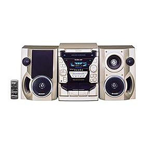
Illustration: CD-BA1700H
SAFETY PRECAUTION FOR SERVICE MANUAL ........................................................................................................... 2
IMPORTANT SERVICE NOTES (CD-BA1700H FOR U.K. ONLY) ................................................................................... 2
SPECIFICATIONS ............................................................................................................................................................. 3
NAMES OF PARTS ........................................................................................................................................................... 4
OPERATION MANUAL ...................................................................................................................................................... 6
DISASSEMBLY .................................................................................................................................................................. 9
REMOVING AND REINSTALLING THE MAIN PARTS ................................................................................................... 12
ADJUSTMENT ................................................................................................................................................................. 14
NOTES ON SCHEMATIC DIAGRAM .............................................................................................................................. 20
TYPES OF TRANSISTOR AND LED ............................................................................................................................... 20
BLOCK DIAGRAM ........................................................................................................................................................... 21
SCHEMATIC DIAGRAM / WIRING SIDE OF P.W.BOARD .............................................................................................. 24
VOLTAGE ........................................................................................................................................................................ 38
WAVEFORMS OF CD CIRCUIT ...................................................................................................................................... 39
TROUBLESHOOTING ..................................................................................................................................................... 40
FUNCTION TABLE OF IC ................................................................................................................................................ 44
FL DISPLAY ...................................................................................................................................................................... 50
SERVICE MANUAL
CONTENTS
SHARP CORPORATION
- 1 -
CD-BA160H
CD-BA1700H
CD-BA160H mini component system consisting of
CD-BA160H (main unit) and CP-BA160H (speaker system).
CD-BA1700H mini component system consisting of
CD-BA1700H (main unit), CP-BA1700H (front speakers)
and GBOXS0041AWM1 (surround speakers).
• In the interests of user-safety the set should be restored to its
original condition and only parts identical to those specified be
used.
• Note for users in U.K.
Recording and playback of any material may require consent,
which SHARP is unable to give. Please refer particularly to the
provisions of Copyright Act 1956, the Dramatic and Musical
Performers Protection Act 1956, the Performers Protection Acts
1963 and 1972 and to any subsequent statutory enactments and
orders.
DIFFERENCE BETWEEN
CD-BA160H AND CD-BA1700H
SECTION
CD Digital Output
None
Speaker terminal
2 speaker
Surround speaker
None
This document has been published to be used
for after sales service only.
The contents are subject to change without notice.
CD-BA160H/1700H
No. S4024CDBA160H
CD-BA160H
CD-BA1700H
Used
4 speaker
Used
Page
Advertisement
Table of Contents

Related Manuals for Sharp CD-BA160H


Summary of Contents for Sharp CD-BA160H
-
Page 1: Table Of Contents
• Note for users in U.K. Recording and playback of any material may require consent, which SHARP is unable to give. Please refer particularly to the provisions of Copyright Act 1956, the Dramatic and Musical Performers Protection Act 1956, the Performers Protection Acts 1963 and 1972 and to any subsequent statutory enactments and orders. -
Page 2: Safety Precaution For Service Manual
CD-BA160H/1700H SAFETY PRECAUTION FOR Laser Diode Properties Material: GaAIAs SERVICE MANUAL Wavelength: 780 nm Emission Duration: continuous Laser Output: max. 0.6 mW Precaution to be taken when replacing and servicing the Laser Pickup. The AEL (Accessible Emission Level) of Laser Power Output for this model is specified to be lower than Class I Requirements. -
Page 3: Specifications
4.76 cm/sec. (1-7/8 ips.) 6.4 kg (14.0 lbs.) Weight: Signal/noise ratio: 55 dB (TAPE 1, playback) 50 dB (TAPE 2, recording/playback) Amplifier section (CD-BA160H) Wow and flutter: 0.35 % (DIN 45 511) PMPO; 320 W Output power: (For Europe) Wow and flutter: 0.3 % (WRMS) -
Page 4: Names Of Parts
CD-BA160H/1700H NAMES OF PARTS CD-BA160H/1700H Front panel 31 32 22 23 24 25 19 20 21 41 42 28. Spectrum Analyzer/Volume Level Indicator 1. (CD) Disc Tray 2. (TUNER) Programme Type/Traffic Information 29. Extra Bass Indicator 30. RDS Indicator Search Button 3. - Page 5 CD-BA160H/1700H CD-BA160H/1700H CD-BA160H/1700H Rear panel (Illustration: CD-BA1700H) Remote control 1. AC Power Input Socket 2. CD Digital Output Socket (CD-BA1700H Only) 13 14 15 16 17 18 3. FM 75 Ohms Aerial Socket 4. AM Loop Aerial Socket 5. Video/Auxiliary (Audio Signal) Input Sockets 6.
-
Page 6: Operation Manual
CD-BA160H/1700H OPERATION MANUAL – 6 –... - Page 7 CD-BA160H/1700H – 7 –...
- Page 8 CD-BA160H/1700H – 8 –...
-
Page 9: Disassembly
CD-BA160H/1700H DISASSEMBLY CD-BA160H/1700H Caution on Disassembly Follow the below-mentioned notes when disassembling Front Panel (A1)x2 the unit and reassembling it, to keep it safe and ensure ø3x12mm Top Cabinet excellent performance: 1. Take cassette tape and compact disc out of the unit. - Page 10 CD-BA160H/1700H (J2)x1 Tape (N1) x3 Mechanism Disc Tray Front Panel Display PWB (J1)x15 ø3x10mm (N1) x3 Open (K1)x6 Cassette CD Player Unit ø3x10mm Holder (Lift/Right) Figure 10-4 Headphones (L1)x1 Tape (P1)x1 ø3x10mm Mechanism ø3x8mm (P3)x2 Figure 10-1 CD Servo Disc Tray...
- Page 11 CD-BA160H/1700H CP-BA160H/1700H (Front Speaker) PROCEDURE STEP REMOVAL FIGURE Woofer/ 1. Front Panel .... (A1) x1 11-1 Sub Woofer 2. Screw ..... (A2) x8 11-2 Tweeter 1. Screw ..... (B1) x2 11-2 Speaker Woofer (A1)x1 (A2)x4 ø4x12mm Woofer (A2)x4 ø4x12mm Sperker (B1)x2 ø3x10mm...
-
Page 12: Removing And Reinstalling The Main Parts
CD-BA160H/1700H REMOVING AND REINSTALLING THE MAIN PARTS TAPE MECHANISM SECTION TAPE2 Perform steps 1 to 8 and 10 of the disassembly method to Record/Playback Head remove the tape mechanism. How to remove the record/playback and erase heads (Tape 2) (See Fig. 12-1) 1. -
Page 13: Cd Mechanism Section
CD-BA160H/1700H How to remove the motor (See Fig. 13-1) Motor 1. Remove the belt. 2. Remove the screws (F1) x 2 pcs., to remove the motor. (F1) x2 Ø 2.6 x 5mm TAPE2 Figure 13-1 CD MECHANISM SECTION Perform steps 1, 2, 3, 12, 13, 14 and 15 of the disassembly method to remove the CD mechanism. -
Page 14: Adjustment
CD-BA160H/1700H ADJUSTMENT MECHANISM SECTION TUNER SECTION • Driving Force Check fL: Low-range frequency fH: High-range frequency Torque Meter Specified Value • AM IF/RF Play: TW-2111 Tape 1: Over 80 g Tape 2: Over 80 g Signal generator: 400 Hz, 30%, AM modulated... -
Page 15: Test Mode
CD-BA160H/1700H CD SECTION TEST MODE • • Adjustment Setting the test mode Any one of test mode can be set by pressing several keys as Since this CD system incorporates the following automatic fallows. adjustment functions, readjustment is not needed when <X-BASS>... - Page 16 CD-BA160H/1700H ASPM, summary operation Hold down the ASPM button for 3 more second. Displayed the TTL quantity of memorized “ASPM” blinks in the display. stations by ASPM operation on this time. And return to the previous receiving freq. automatically. No operate.
- Page 17 Preset memory takes priority of switching TN—ON station. Therefore ASPM is usefull not only for PTY search but also for rapid EON switching. Anyway CD-BA160H/1700H EON is basically stand-by and receiving method, along with the Guidelines for EON implementa- tion.
- Page 18 CD-BA160H/1700H EON summary notice for reference 1. EON-TI/PTY EON stand-by can be set, only when EON ind. lights up. While EON ind. goes out (NO EON STATION), EON stand-by can't be set. If the EON button is pressed, then “NO EON” is indication the display.
- Page 19 CD-BA160H/1700H – 19 –...
-
Page 20: Notes On Schematic Diagram
CD-BA160H/1700H NOTES ON SCHEMATIC DIAGRAM • The indicated voltage in each section is the one measured • Resistor: by Digital Multimeter between such a section and the chas- To differentiate the units of resistors, such symbol as K and sis with no signal given. -
Page 21: Block Diagram
CD-BA160H/1700H CD-BA1700H ONLY IC99 DISC OPEN/ TOTX178A CLAMP NUMBER CLOSE OPTICAL FIBER TO MAIN SECTION DATA LINK TO DISPLAY SECTION (TO IC401) LOADING MOTOR BI99 CNS99 9 10 CNP12 CNS4 CNP5 CNP4 45 46 47 48 32 31 30 75 76... - Page 22 CD-BA160H/1700H SO301A FM ANTENNA FM IF TERMINAL CF302 CF301 Q301 FE301 FM FRONT END FM IF +5.1V T351 CF351 CF352 FM IF AM LOOP ANTENNA AM MIX AM IF MO/ST IC303 FM IF DET/FM MPX./AM IF CNP302 LA1832S FM/AM MPXIN...
- Page 23 CD-BA160H/1700H FL701 FL DISPLAY LED722 1 2 3 13 14 28 29 47 48 49 Q601~ Q604 Q603 MOTOR TAPE Q607 Q608 DRIVER MOTOR Q606 TO TAPE MECHANISM Q605 56 55 54 53 52 51 50 49 47 46 45 44 43 42 41 40...
-
Page 24: Schematic Diagram / Wiring Side Of P.w.board
CD-BA160H/1700H IC401 C404 C405 LC75341 AUDIO PROCESSOR 100/16 0.022 R-CH TO CD SERVO A_GND L-CH CNP11 C407 CD_GND 10/50 VREF P33 12-D C409 INTERFACE ROUT LOUT R415 C411 (ML) 0.1( 3.9K 0.1 (ML) LBASS RBASS R401 R409 C413 C414 LTRE 0.0027... - Page 25 CD-BA160H/1700H MAIN PWB-A1(1/3) AUX IN L-CH R419 C429 R421 5.6K 390P SO401 R420 VIDEO/AUX C430 R422 5.6K 390P C406 R-CH 22/50 VREF C408 10/50 ROUT C410 R416 0.1(ML) 3.9K BASS C412 C414 0.1(ML) RTRE 0.0027 C440 C418 0.001 1/50 C420 SEL0 4.7/50...
- Page 26 CD-BA160H/1700H IC901 STK40204(2Ch) POWER AMP. C902 C901 470P 470P R919 R918 100(1/4W) R920 (1/4W) C903 Fusible Fusible R901 C910 100/50 R903 C905 R931 47/50 R934 R907 0.1(1W) R908 0.1(1W) R933 D903 C907 R909 DS1SS133 0.022 D901 DS1SS133 4.1V C935 R910...
- Page 27 CD-BA160H/1700H R975 FM SIGNAL 4.7(1/2W) C971 47/50 – D971 M901 R971 DS1SS133 FAN MOTOR R973 C972 R972 10/50 MOTOR DRIVER RL951 FW951 RELAY JK951 R952 330(1/2W) HEADPHONES L951 2.2uH C952 C951 R951 220P 330(1/2W) 220P D951 DS1SS133 HEADPHONES PWB-A3 Q951 0.2V...
- Page 28 CD-BA160H/1700H C302 0.001 AM TRACKING fL T303 AM ANTENNA C331 C330 0.047 15P(UJ) C323 0.022 C338 C332 0.001 0.022 D301 DS1SS133 AM LOOP D302 DS1SS133 ANTENNA AM BAND VD301 SVC348S COVERAGE fL C335 R358 560P T306 3.9K L341 BALUN R350 2.7K...
- Page 29 CD-BA160H/1700H MAIN PWB-A1 (3/3) FM SIGNAL AM SIGNAL C373 0.015 C371 1/50 L354 LOW PASS FILTER R350 C372 2.7K C369 1/50 C367 (UJ) 1/50 15 14 13 IC303 LA1832S FM IF DET./FM MPX./AM IF CNP304 RDS PWB-D RT48 10 11...
- Page 30 CD-BA160H/1700H DISPLAY PWB-A4 FL701 FL DISPLAY 49 48 47 44 43 42 41 40 39 38 37 36 35 34 33 32 31 30 29 28 27 26 25 24 23 16 15 14 13 12 11 10 9 8 7 6 3...
- Page 31 CD-BA160H/1700H 8 7 6 3 2 1 CD INT WRQ(DSP) C621 1/50 CD CE TO CD SERVO PWB CD DO CNP12 CD DI P33 11-F CD CLK RES OUT 94 95 96 97 98 99 CLAMP SW NO USE S-BUSY...
- Page 32 CD-BA160H/1700H CD SERVO PWB-C CD SIGNAL Vref TIN1 FIN1 FIN2 0.047 TIN2 LA9235M SERVO AMP. 0.47/6.3 2.2/50 FIN1 LA9235M 100P ODRV FIN2 RFSW AGCON 6.8K TIN1 (CH) 47/10 0.01 TIN2 100/10 0.01 REF1 0.0047 10/16 VREF 0.33 ODRV 0.33 RFEV...
-
Page 33: Digital Output
CD-BA160H/1700H 100P 0.01 100P 100P 100P 100P 100P 100P 2.2µ˙ VDD5V 80 79 78 77 76 75 74 73 72 71 70 69 68 67 66 65 EFMO 0.047 PDO1 COMMAND GENERAL INTERFACE 1.5M 100/10 SBCK PDO2 FRAME LC78641E 2.2/50... - Page 34 CD-BA160H/1700H SO902 SPEAKER TERMINALS (FOR CD-BA1700H) SO901 CD-BA1700H ONLY FRONT SPEAKER SO301A SO401 TERMINALS SURROUND FM ANTENNA VIDEO/ AM LOOP (FOR CD-BA160H) SPEAKER TERMINAL ANTENNA R-CH L-CH L-CH R-CH R-CH L-CH L-CH R-CH L-CH R-CH MAIN PWB-A1 CNP302 C301 L341...
- Page 35 CD-BA160H/1700H HEADPHONES PWB-A3 CNP951 FW951 JK951 HEADPHONES RDS PWB-D CT28 COLOR TABLE CT29 BROWN CT27 RD(R) 13 15 ICT21 ORANGE XT21 12 10 YELLOW RT21 GREEN CT23 CT25 BLUE RT33 CT22 VIOLET RT34 CT24 GRAY B C E CT21 CT43...
- Page 36 CD-BA160H/1700H SW601 SW602 C621 ON/STAND-BY D620 CLOCK SW617 SW616 D616 DISPLAY TAPE R704 PWB-A2 R716 CNS701 1 2 3 IC704 3 2 1 SW626 Q609 TUNING C629 R711 SW618 SW628 SW627 D621 TUNING TUNER VIDEO/ DOWN (BAND) D618 SW603 C628...
- Page 37 CD-BA160H/1700H TAPE TAPE MECHANISM CD LOADING MECHANISM ASSEMBLY(2/2) PWB-G MOTOR OPEN/ CLOSE PWB-F CLAMP CD-BA1700H COLOR TABLE ONLY BROWN – RD(R) DIGITAL ORANGE OUTPUT YELLOW TAPE MOTOR LOADING PWB-A4 GREEN MOTOR IC99 BLUE OPTICAL FIBER VIOLET DATA LINK GRAY B A + -...
-
Page 38: Voltage
CD-BA160H/1700H VOLTAGE IC701 IC101 IC901 IC702 VOLTAGE VOLTAGE NO. VOLTAGE VOLTAGE NO. VOLTAGE VOLTAGE NO. VOLTAGE 4.29V 1.6V 0.7V 0V(0V) 4.29V 1.6V 0V(0V) 4.29V 1.6V 0.5V(0.5V) 4.29V 1.6V 1.9V(1.9V) 34.4V -11.0 4.29V 1.6V 0V(0V) -32.9V 3.3V 4.29V 0V(0V) 1.6V 2.4V 0V(0V) 1.2V... -
Page 39: Waveforms Of Cd Circuit
CD-BA160H/1700H WAVEFORMS OF CD CIRCUIT Stopped Stopped 1999/04/05 17:33:17 CH1=500mV CH3=500mV 500ms/div CH1=500mV CH3=1V CH4=1V 500ms/div DC 10:1 DC 10:1 (500ms/div) DC 10:1 DC 10:1 DC 10:1 (500ms/div) NORM:20kS/s NORM:20kS/s IC2 1 PDO1 IC2 24 PDO1 IC2 2 PDO2 PDO2... -
Page 40: Troubleshooting
CD-BA160H/1700H TROUBLE SHOOTING When the CD does not function When the CD section does not operate when the objective lens of the optical pickup is dirty, this section may not operate. Clean the objective lens, and check the playback operation. When this section does not operate even after the above step is taken, check the following items. - Page 41 CD-BA160H/1700H (1) Focus-HF system check Stopped CH1=500mV CH3=500mV 500ms/div Although a CD is inserted and the cover is closed, "NO DC 10:1 DC 10:1 (500ms/div) NORM:20kS/s DISC" is displayed. Press the OPEN/CLOSE switch (SW1) without inserting a disc, and try starting the playback operation.
- Page 42 CD-BA160H/1700H (2) Tracking system check Check the TE waveform at pin 18 on IC1. The tracking servo is not activated. If the waveform shown in Figure 42-1 appears and soon after Check the peripheral circuits at pins 18 and 19 on IC1, pin 23 on NO DISC appears.
- Page 43 CD-BA160H/1700H (4) PLL system check Stopped 1999/04/05 17:33:17 CH1=500mV CH3=1V CH4=1V 500ms/div DC 10:1 DC 10:1 DC 10:1 (500ms/div) NORM:20kS/s When a disc is loaded, start play operation. PDO1 The HF waveform is normal, but the TOC data cannot be PDO2 read.
-
Page 44: Function Table Of Ic
CD-BA160H/1700H FUNCTION TABLE OF IC IC1 VHiLA9235M/-1: Servo Amp. (LA9235M) ODRV FIN1 LA9235M RFSW(NC) FIN2 AGCON 28 RF- TIN1 TIN4 26 N/C 25 PH 24 BH REF1 ODRV 23 GND PH/BH 22 RFEV VREF 21 FE- 20 FE LDON 19 TE-... - Page 45 CD-BA160H/1700H IC2 VHiLC78641E-1: Servo/Signal Control (LC78641E) (1/2) Terminal Name Input/Output Setting in Reset Function Pin No. PDO1 Output – For PULL Phase-comparison output terminal for built-in VOC control. PDO2 Output – Phase-comparison output terminal for built-in VOC control. Rough servo : OFF, phase servo : ON.
- Page 46 CD-BA160H/1700H IC2 VHiLC78641E-1: Servo/Signal Control (LC78641E) (2/2) Terminal Name Input/Output Setting in Reset Function Pin No. LVDD – – L channel Power terminal for L channel. LCHO Output 1/2VDD D/A converter L channel output terminal. LVSS – – Ground terminal for L channel. Surely connected to 0V.
- Page 47 CD-BA160H/1700H IC701 RH-iX0329AWZZ: System Microcomputer (IX0329AW) (1/2) Pin No. Port Name Terminal Name Input/Output Function — (+) Power supply NO USE — Commijntcate to MPEG µ–COM S-BUSY Output T–BIAS Output Tape record BIAS T–T1/T2 Output Tape T1/T2 change REC/PLAY Output Tape REC/PLAY change CD DSP reset &...
- Page 48 CD-BA160H/1700H IC701 RH-iX0329AWZZ: System Microcomputer (IX0329AW) (2/2) Pin No. Port Name Terminal Name Input/Output Function P120 PLAY SW_B Input Play switch for T2 P119 Input Tape2 A–side full proof P118 Input Tape2 B_side full proof P117 MIC IN Input Mic switch...
- Page 49 CD-BA160H/1700H IC401 VHiLC75341/-1: Audio Processor (LC75341) LOUT ROUT LBASS RBASS LTRE RTRE LSELO RSELO R1 R2 24 23 22 21 20 19 18 17 16 15 14 13 LC75341 10 11 12 Figure 49 BLOCK DIAGRAM OF IC – 49 –...
-
Page 50: Fl Display
CD-BA160H/1700H FL701 VVKBJ749GNK-1: FL Display B7 B6 B5 B4 B3 B4 B5 B6 B7 Figure 50 FL DISPLAY – 50 –... -
Page 51: Parts Guide
PARTS GUIDE CD-BA160H MODEL CD-BA1700H CD-BA160H mini component system consisting of CD-BA160H (main unit) and CP-BA160H (speaker system). CD-BA1700H mini component system consisting of CD-BA1700H (main unit), CP-BA1700H (front speakers) and GBOXS0041AWM1 (surround speakers). “HOW TO ORDER REPLACEMENT PARTS” To have your order filled promptly and correctly, please furnish the For U.S.A. - Page 52 CD-BA160H/1700H PRICE PRICE DESCRIPTION PARTS CODE PARTS CODE DESCRIPTION RANK RANK ZD803 VHEDZ130BSB-1 AB Zener,13V,DZ13BSB CD-BA160H/1700H ZDT21 VHEDZ5R1BSB-1 AC Zener,5.1V,DZ5.1BSB INTEGRATED CIRCUITS FILTERS VHILA9235M/-1 AQ Servo Amp.,LA9235M CF301,302 RFILF0072AFZZ AG FM IF VHILC78641E-1 AV Servo/Signal Control,LC78641E CF351 RFILF0003AWZZ AK FM IF...
- Page 53 CD-BA160H/1700H PRICE PRICE DESCRIPTION PARTS CODE DESCRIPTION PARTS CODE RANK RANK AB 47 µF,10V,Electrolytic AB 47 µF,16V,Electrolytic VCEAZA1AW476M J C394 VCEAZA1CW476M J AA 0.01 µF,16V AA 0.022 µF,25V VCTYPA1CX103K C395 VCTYMN1EF223Z AA 0.001 µF,50V AB 100 µF,10V,Electrolytic VCKYTV1HB102K C396 VCEAZA1AW107M J AB 47 µF,10V,Electrolytic...
- Page 54 CD-BA160H/1700H PRICE PRICE PARTS CODE DESCRIPTION PARTS CODE DESCRIPTION RANK RANK AB 22 µF,50V,Electrolytic C930,931 VCEAZA1HW226M J R135,136 VRD-MN2BD103J AA 10 kohm,1/8W [CD-BA1700H Only] R137 VRD-MN2BD153J AA 15 kohms,1/8W AA 0.001 µF,50V C932 VCKYPA1HB102K R138 VRD-ST2CD153J AA 15 kohms,1/6W [CD-BA1700H Only]...
- Page 55 SO801 QSOCA0204AWZZ J AF Socket,AC Input R903,904 VRD-ST2CD821J AA 820 ohms,1/6W SO901 QTANA0417AWZZ J AE Terminal,Speaker R905,906 VRD-ST2CD102J AA 1 kohm,1/6W [CD-BA160H Only] R907,908 VRN-VV3AAR10J 0.1 ohm,1W SO902 QTANA0808AWZZ J Terminal,Speaker R909,910 VRD-ST2CD102J AA 1 kohm,1/6W [CD-BA1700H Only] R911,912 VRD-ST2CD103J...
- Page 56 AC Switch,Key Type [STOP] GITAR0570AWSA Rear Panel SW625 92LSWICH1401AT J AC Switch,Key Type [CD-BA1700H for U.K.] [RECORD/PAUSE] GITAR0575AWSA AG Rear Panel [CD-BA160H] SW626 92LSWICH1401AT J AC Switch,Key Type [TUNING UP] GITAR0600AWSA AG Rear Panel SW627 92LSWICH1401AT J AC Switch,Key Type [VIDEO/AUX]...
- Page 57 AY Speaker Box Ass’y,Left TINSE0312AWZZ AG Operation Manual 92L051-0100 AY Speaker Box Ass’y,Right [CD-BA1700H for U.K.] 92L394-0056 AC Foot Cushion TINSZ0550AWZZ AS Operation Manual [CD-BA160H] 92L394-0059 AC Port Cushion TINSZ0569AWZZ AS Operation Manual 92L351-0375 AB Label,Specifications [CD-BA1700H for Europe] 92L319-0027...
- Page 58 CD-BA160H/1700H CD-BA160H/1700H 306-2 306-1 306-3 703x2 305x2 PWB-E Figure 7 CD MECHANISM EXPLODED VIEW – 7 –...
- Page 59 CD-BA160H/1700H CD-BA160H/1700H PWB-A1 CD-BA1700H ONLY 609x2 PWB-D 202-1 618x2 PWB- 608x2 614x3 IC901 614x2 Silicon 202-2 IC851 602x10 231x6 grease 607x3 PWB-A2 BELT CONNECTION IC841 201-12 Q831 201-11 Motor Tape FF/REW Flywheel Motor Roller Ass'y 201-14 Ass'y Tape2 Flywheel 201-13...
- Page 60 CD-BA160H/1700H CD-BA160H/1700H 604x2 604x2 MECHANISM PWB-F 250x4 239x3 204-2 204-1 204-3 PWB-C Figure 9 CABINET EXPLODED VIEW (2/2) – 9 –...
- Page 61 CD-BA160H/1700H CP-BA160H/1700H Front Speaker 904(Left) 905(Right) (with Capacitor C1,2) SP1(L-CH) SP2(R-CH) 912x4 911x2 SP5(L-CH) SP6(R-CH) 910x4 912x4 SP3(L-CH) 907x2 SP4(R-CH) 901(Left) 902(Right) (913) C1,2 Capacitor 2.2µF,50V (N.P.) 907x2 WOOFER SP1(L-CH) SP2(R-CH) WOOFER SP1(L-CH) TWEETER SP2(R-CH) SP5(L-CH) C1,2 Capacitor SP6(R-CH) 2.2µF,50V...
- Page 62 CD-BA160H/1700H GBOXS0041AWM1 Surround Speaker (CD-BA1700H Only 905x6 SP1(L-CH) SP2(R-CH) SP1(L-CH) SP2(R-CH) Figure 11 SPEAKER EXPLODED VIEW (2/2) – 11 –...
-
Page 63: Packing Method (Cd-Ba1700H For U.k. Only)
CD-BA160H/1700H PACKING METHOD (CD-BA1700H FOR U.K. ONLY) Setting position of switches and knobs Tape Mechanism STOP 15 Polyethylene Bag,Accessories 92LBAG1460C1 Polyethylene Bag,Unit SPAKP0013AWZZ 16 Polyethylene Bag, 92LBAG1770A Polyethylene Bag,Front Speaker 92L411-0075 AC Power Supply Cord Packing Add.,Left/Right SPAKA0245AWZZ 17 FM Antenna 92LFANT1535A Packing Add.,Top/Bottom... - Page 64 CD-BA160H/1700H © COPYRIGHT 2000 BY SHARP CORPORATION ALL RIGHTS RESERVED. No part of this publication may be reproduced, stored in a retrieval system, or transmitted in any from or by any means, electronic, mechanical, photocopying, recording, or otherwise, without prior written permission of the publisher.
Need help?
Do you have a question about the CD-BA160H and is the answer not in the manual?
Questions and answers