
Related Manuals for AirWild Hobbies Almost-ready-to-fly 29% Extra 260

Summary of Contents for AirWild Hobbies Almost-ready-to-fly 29% Extra 260
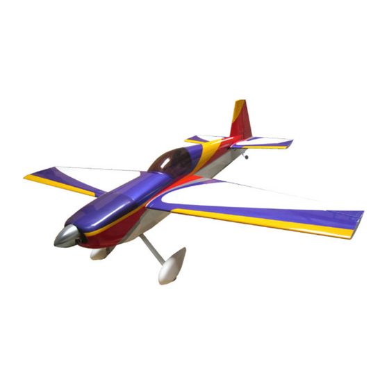
- Page 2 White Hanger 9 HANU870 White Hanger 9 HANU866 True Red Yellow Hanger 9 HANU1884 Cub Yellow Silver Hanger 9 HANU881 Silver Purple Hanger 9 HANU847 Pearl Purple Doc. No.# AW70-105-01, Rev. 3 Copy Right 2006, AirWild Hobbies, Inc. Page 2...
- Page 3 Blind Nut, Stainless Steel, M3 Flat Washer, Stainless Steel, M3 Flat Washer, Stainless Steel, M4 Pan Head Wood Screw, 3MMx15MM EFP Control Horn Tail Wheel Bracket CA Hinge Assembly Manual Doc. No.# AW70-105-01, Rev. 3 Copy Right 2006, AirWild Hobbies, Inc. Page 3...
- Page 4 Carbon Fiber Push Rod, Semi Flex (throttle Sullivan SUL580 Ignition push rod) Universal Ball Joint, 2-56 Threaded DuBro DUB181 Mini Digital Metal Gear Servo, 60 oz. In. (recommended) Doc. No.# AW70-105-01, Rev. 3 Copy Right 2006, AirWild Hobbies, Inc. Page 4...
- Page 5 Disclaimer: This list is provided only as a reference. AirWild Hobbies, Inc. does not in any fashion guarantee nor assumes product liabilities of their uses by customers. Please consult your local hobby shops or contact manufacturers directly for specific information. Buyer assumes all risks of use.
- Page 6 To purchase these packages please contact AirWild Hobbies directly. This hardware package is provided as a convenience to end users. AirWild Hobbies, Inc. does not in any fashion guarantee nor assumes product liabilities of their uses by customers.
-
Page 7: Engine Mounting
Under no circumstances never disassemble, cut into, nor break up engine box structure to adapt for your particular engine. Failure to comply will void manufacturer warranty. Dimensional References – Engine Installation Doc. No.# AW70-105-01, Rev. 3 Copy Right 2006, AirWild Hobbies, Inc. Page 7... - Page 8 Make sure your DA aluminum stand-offs is the standard-size, 2.5” set. Fabricate four (4) 0.25” (6.35mm) thick spacers out of 5-layer, 0.25” thick plywood. Install spacer between stand-off and fire wall. Doc. No.# AW70-105-01, Rev. 3 Copy Right 2006, AirWild Hobbies, Inc. Page 8...
- Page 9 Drill a hole through the bottom surface to route the battery connector of the ignition module to the inside of the engine box where the ignition battery will situate. Doc. No.# AW70-105-01, Rev. 3 Copy Right 2006, AirWild Hobbies, Inc. Page 9...
- Page 10 When done, find a spot to mount your SmartFly optical ignition kill switch. Use adhesive back foam tape or Velcro tapes to secure it. You are done with this part of installation. Doc. No.# AW70-105-01, Rev. 3 Copy Right 2006, AirWild Hobbies, Inc. Page 10...
- Page 11 Sullivan Product’s Twist-Tie Clamps (P/N #488) is a great choice for this application which is available from AirWild Hobbies / AirWild Pilot Shop online. Basic Setup of Fuel Delivery System Most gasoline engines are equipped with a suction based carburetor such as Walbro or Tilliston.
- Page 12 Use Sullivan #580 CF push rod kit to fabricate throttle push rod. Cut both inner CF push rod and outer housing to length. We recommend DuBro #181, Universal Ball Joint, for end-point attachment to both throttle servo arm and engine throttle arm. Doc. No.# AW70-105-01, Rev. 3 Copy Right 2006, AirWild Hobbies, Inc. Page 12...
- Page 13 Center point of the blind nut is about 5mm from the edge of the fuselage. Transfer blind nut locations to cowl. Drill holes in cowl to accept M3 socket head screw for securing the cowl. Doc. No.# AW70-105-01, Rev. 3 Copy Right 2006, AirWild Hobbies, Inc. Page 13...
- Page 14 Follow instructions provided in the Sullivan Tail Wheel Assembly package to mount it to the fuselage. For convenience you can mount the assembly using two wood screws instead. Doc. No.# AW70-105-01, Rev. 3 Copy Right 2006, AirWild Hobbies, Inc. Page 14...
- Page 15 Now use your Xactor blade and cut into the balsa core to deepen the slot. Your goal is to create a through slot from one side of the rudder to the other. Cut a little bit at a time Doc. No.# AW70-104-01, Copy Right 2004, AirWild Hobbies, Inc. page 15...
- Page 16 Make sure that vertical fin and rudder are budding against each other, thus eliminating any gap. Maintain a small gap between top of Doc. No.# AW70-104-01, Copy Right 2004, AirWild Hobbies, Inc. page 16...
- Page 17 Hook up cables in parallel, to rudder servo arm and rudder control horns. Adjust cable tension accordingly by dialing available threads in the Cable Attachment Fitting till adequate cable tension. Doc. No.# AW70-104-01, Copy Right 2004, AirWild Hobbies, Inc. page 17...
- Page 18 You will have to shorten the EFP horns accordingly. Enlarge width of the slot (not length) if needed. Align horns to match illustration on the right. Do not tag glue them yet. Doc. No.# AW70-104-01, Copy Right 2004, AirWild Hobbies, Inc. page 18...
- Page 19 Hook up push rod to servo arm and EFP control horns. Adjust the turnbuckle push rod until elevator is in neutral and servo arm is at 90 degrees to the servo body. Doc. No.# AW70-104-01, Copy Right 2004, AirWild Hobbies, Inc. page 19...
- Page 20 Trial fit both control horns into the slots for fitment. Enlarge width of the slot (not length) if needed. Align horns to match illustration on the right. Do not tag glue them at this time. Doc. No.# AW70-104-01, Copy Right 2004, AirWild Hobbies, Inc. page 20...
- Page 21 14. Hook up push rod to servo arm and EFP control horns. Adjust the turnbuckle push rod until aileron is in neutral and servo arm is at 90 degrees to the servo body. Doc. No.# AW70-104-01, Copy Right 2004, AirWild Hobbies, Inc. page 21...
- Page 22 “piggybacking” on top of the fuel tank. If your components are “heavier” than our reference selection, move the receiver battery around to find the best balance point for your setup. Doc. No.# AW70-104-01, Copy Right 2004, AirWild Hobbies, Inc. page 22...
- Page 23 PCM radio transmitters come standard with necessary channel mixing functions needed for the following channel setup. Once again this setup is merely a recommendation. Feel free to adopt your preferred configuration. Doc. No.# AW70-104-01, Copy Right 2004, AirWild Hobbies, Inc. page 23...
- Page 24 Once again please consider the above information as only a starting point of your control adjustment. After you have a feel for the behavior of the aircraft, you can then fine-tune the throw to match your exact flying style. Doc. No.# AW70-104-01, Copy Right 2004, AirWild Hobbies, Inc. page 24...
- Page 25 Go into a power-off vertical dive from high altitude. If model pulls to canopy, increase wing or stab incidence. If airplane pulls to belly, then reduce wing or stab incidence. Doc. No.# AW70-104-01, Copy Right 2004, AirWild Hobbies, Inc. page 25...
- Page 26 Notes: This space is intentionally left blank. Doc. No.# AW70-104-01, Copy Right 2004, AirWild Hobbies, Inc. page 26...
- Page 27 Notes: This space is intentionally left blank. Doc. No.# AW70-104-01, Copy Right 2004, AirWild Hobbies, Inc. page 27...
- Page 28 Doc. No.# AW70-104-01, Copy Right 2004, AirWild Hobbies, Inc. page 28...
Need help?
Do you have a question about the Almost-ready-to-fly 29% Extra 260 and is the answer not in the manual?
Questions and answers