Table of Contents
Advertisement
Quick Links
Advertisement
Table of Contents

Summary of Contents for Lodestar LS1130
- Page 1 INSTRUCTION MANUAL Model LS1130 Single Output DC Power Supply...
-
Page 2: General Safety Summary
GENERAL SAFETY SUMMARY Review the following safety precautions to avoid injury and prevent damage to this product and any product connected to it. To avoid potential hazards, use this product only as specified. To avoid fire or personal injury: Use proper power cord. Use only the power cord supplied with this product or a power cord that is specified for the country of use. -
Page 3: Table Of Contents
Table of Content 1. Product Introduction..............5 1.1 Description..................5 1.2 Key Features ..................5 2. Specifications...................6 3. Safety Information and Installation..........7 3.1 Unpacking the instrument ..............7 3.2 Checking the Line Voltage..............7 3.2 Cooling....................7 4. Panel Introduction................8 4.1 Front Panel ..................8 4.2 Rear Panel ................... -
Page 4: Safety Terms And Symbols
SAFETY TERMS AND SYMBOLS These terms and symbols may appear on the product or in the user manual. ________________________________________________ WARNING: Warning statements identify condition or practices that could result in injury or loss of life. ¯¯¯¯¯¯¯¯¯¯¯¯¯¯¯¯¯¯¯¯¯¯¯¯¯¯¯¯¯¯¯¯¯¯¯¯¯¯¯¯¯¯¯¯¯¯¯¯ ________________________________________________ CAUTION: Caution statements identify conditions or practices that could result in damage to this product or other property. -
Page 5: Product Introduction
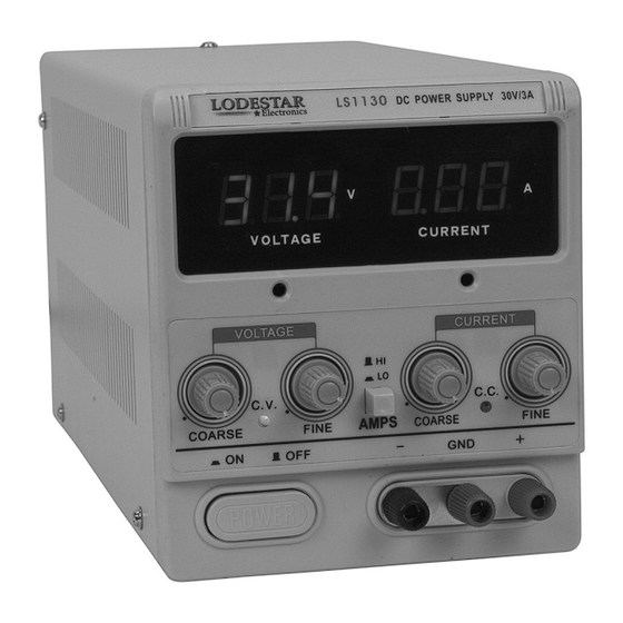
1 PRODUCT INTRODUCTION 1.1 Description The Lodestar Electronics model LS1130 is a high quality, general purpose Single Output Regulated DC Power Supply. It provides 0-30 Volts DC output, adjustable with both coarse and fine voltage controls for precise setting of the desired value. The current output is rated 0-3 Amps, adjustable with both coarse and fine current controls. -
Page 6: Specifications
2. SPECIF CATIONS Output Voltage 0 – 30V, Coarse and Fine adjustment Output Current 0 – 3A, Coarse and Fine Adjustment Line Regulation ≤ 0.01% + 3mV Load ≤ 0.01% + 3mV (≤ rating current) Regulation ≤ 1mVrms, 5Hz to 1MHz (rating current ≤ Ripple &... -
Page 7: Safety Information And Installation
3. SAFETY INFORMATION AND INSTALLATION 3.1 Unpacking the Instrument The product has been fully inspected and tested before shipping from the factory. Upon receiving the instrument, immediately unpack and inspect it for any damages that might have been sustained during transportation. If any sign of damage is found, notify your local distributor immediately. -
Page 8: Panel Introduction
4. PANEL INTRODUCTION 4.1 Front panel (1) green LED Display 3 digit display, continuously monitors voltage. (2) red LED Display 3 digit display, continuously monitors current. (3) Coarse VOLTAGE Control Coarse adjustment of output voltage. Read value on green LED display. - Page 9 (4) C.V. (Constant Voltage) Indicator. Green LED lights when the power supply is in Constant Voltage mode. The power supply regulates the output voltage at the value set by the VOLTAGE controls. (5) Fine VOLTAGE Control Fine adjustment of output voltage. Read value on green LED display. (6) Hi/Low range AMP switch There are 2 ranges of current limiting.
-
Page 10: Rear Panel
4.2 Rear Panel (14) Ventilation fan, ventilation holes (15) Input voltage selector Set switch to corresponding line voltage (16) AC Power Input Connector Connect the AC power cord to this receptacle (17) Fuse Compartment... -
Page 11: Operating Instructions
5. OPERATING INSTRUCTIONS 5.1 General Precautions Avoid using the power supply in ambient temperatures above +40° C. Always allow sufficient air space around the venting hole at the rear of the power supply for effective radiation to prevent internal heat build-up. Do not exceed the voltage rating of the circuit being powered. -
Page 12: Typical Constant Current Operation
Setting Current Limit 1) Determine the maximum safe current for the device to be powered. 2) Temporarily short the (+) and (-) terminals of the power supply together with a test lead. 3) Rotate the COARSE VOLTAGE control away from zero sufficiently for the C.C. indicator to light. -
Page 13: Connecting Two Power Supplies In Series
5.5 Connecting Two Power Supplies in Series Two Model LS1130 power supplies may be connected in series to provide a variable 0-60 volt output. In this configuration the power supply can supply up to 3 amps, see... - Page 14 Load When connected in series, the VOLTAGE controls of each power supply exercise control over a 0-30 volt range. Add the LED display readings together or connect an external voltmeter across the load to determine the total output voltage. Load current may be monitored from either supply;...
- Page 15 When connected in parallel and operating in the constant voltage mode, determine the total load current limit and preset the current limiting for each power supply to half the total load current value. Then when the load is connected, set the VOLTAGE controls on the two power supplies for equal voltage readings.
-
Page 16: Maintenance
6. MAINTENANCE WARNING The following instructions are for use by qualified personnel only. To avoid electrical shock, do not perform any servicing other than what’s described in the operating instructions unless you are qualified to do so. 6.1 Fuse Replacement If the fuse blows, the power lamp indicators will not light and the oscilloscope will not operate. -
Page 17: Service Information
7 SERVICE INFORMATION 7.1 Warranty and Non-Warranty Service Please contact your local distributor for warranty and service instructions. 7.2 Limited 90 day Warranty The company warrants to the original purchaser that its products and the component parts thereof, will be free from defects in workmanship and materials for a period of 90 days from date of purchase from your local distributor. -
Page 18: Appendix
8 APPENDIX 8.1 CE Declaration Declaration of CE Conformity According to EEC directives and NF EN 45014 norm Alternate Manufacturing Responsible Party Manufacturers B&K China 1355 Site B&K Precision Corporation Name: 22820 Savi Ranch Pkwy. Yorba Manufacturer’s Address Linda, CA 92887-4610 USA Declares that the below mentioned product Product Name: Power Supply Part Numbers: LS1330... - Page 19 [intentionally left blank]...
- Page 20 Lodestar Electronics Co. www.lodestarelectronics.com Printed in China Ver. 1.0/0207 © 2007 B&K Precision Corporation...
Need help?
Do you have a question about the LS1130 and is the answer not in the manual?
Questions and answers