Table of Contents
Advertisement
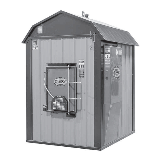
OUTDOOR WOOD FURNACE
OWNER'S MANUAL
For parts and accessories, service or repairs, call your authorized Central Boiler dealer or heating
contractor. Record the information below for future reference.
Model
Dealership Name
Owner Name
Tested &
Portland
Listed By
Oregon USA
US
OMNI-Test Laboratories, Inc.
117-S-12-2 & 117-S-16-4
Serial Number
CL 4030
CL 5036
CL 6048
Installation Date
Phone Number
Save This Manual
For Future Reference
(p/n 9000166 REV. A) - 27-Jan-14
Advertisement
Table of Contents


Need help?
Do you have a question about the CL 4030 and is the answer not in the manual?
Questions and answers