Table of Contents
Advertisement
Advertisement
Table of Contents

Related Manuals for ICT KT-LCD3


Summary of Contents for ICT KT-LCD3
- Page 1 User Manual KT-LCD3 eBike Special Meter WWW.SZKTDZ.COM...
-
Page 2: Table Of Contents
ELECTRIC BICYCLE METER KT—LCD3 Product User Manual Contents Preface……………………………………………………………………………..………. 4 Outlook and Size…………………………………………………………………………... 4 MeterDimension……………………………………………………………………… 4 Button Box Dimension……………………………………………………………….. 4 Main Material and Color………………………………………………….………..5 Wiring Schematic……………………………………………………………….……. 5 Installation Instruction……………………………………………………………….…….. 5 Φ 31.8 handlebar diameters install icon………………………………………..….… 5 Φ 22.2 handlebar diameters install icon……………………………………….….…. 5 Physical installation icon..................... - Page 3 ELECTRIC BICYCLE METER KT—LCD3 Product User Manual Automatic Prompt Interface……………………………………………………..….. 15 Error Code Display…………………………………………………….…..15 Motor Operating Temperature Alarm……………………………………..15 User Project Setting……………………………………………………………………..16 General Project Setting…………………………………………………………………… 16 Maximum Trip Speed…………………………………………………………..16 Wheel Diameter…………………………………………………………………..…. 17 Metric and Imperial Units…………………………………………………………... 18 Exit General Project Setting………………………………………………………..
- Page 4 ELECTRIC BICYCLE METER KT—LCD3 Product User Manual Parameter Copy ........................33 User Setting Note ....................... 35 Version Information……………………………………………………………………… 35 - 3 -...
-
Page 5: Preface
ELECTRIC BICYCLE METER KT—LCD3 Product User Manual Preface The illustrated manual will help you understand and be familiar with the meter function, guiding you on how to operate the meter, how to set the project parameters, how to achieve the best match of the three as motor, controller and meter to improve electronic control performance of the electric motor. -
Page 6: Main Material And Color
ELECTRIC BICYCLE METER KT—LCD3 Product User Manual ○ Main Material and Color PC material is mainly used for KT-LCD3 meter and button box housing, and the housing color is dark gray or white. ○ Wiring Schematic Installation Instruction The meter body and button box are mounted on the handlebars of the electric vehicle, adjusting perspective. -
Page 7: Physical Installation Icon
Physical installation icon Function Overview KT-LCD3 meter provide you with a variety of functions such as vehicle controls and vehicle status digitized displays to meet the trip demands. Trip time display (with displays of a single trip time (TM) and total trip time (TTM));... -
Page 8: Button Definition
ELECTRIC BICYCLE METER KT—LCD3 Product User Manual Button Definition KT-LCD3 meter adopts the structural form with part design between the main part and operating buttons. There are three keys on the operating panel of button box, which are icons of... -
Page 9: Display Interface
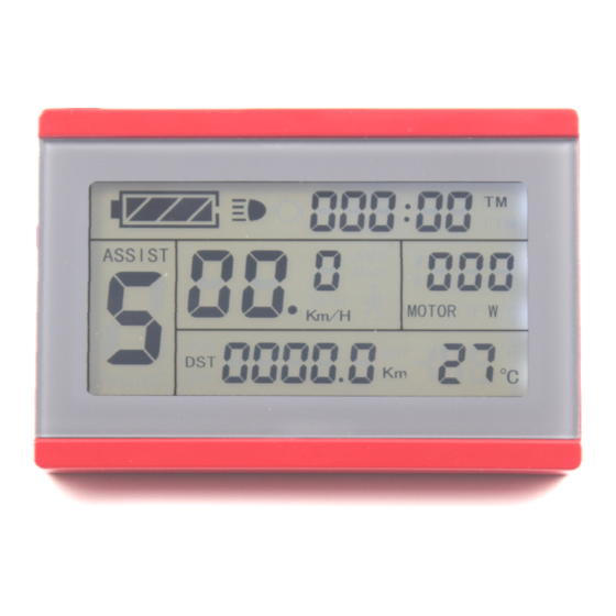
ELECTRIC BICYCLE METER KT—LCD3 Product User Manual ○ Display Interface Display 1 The meter is startup to enter display 1. Display 1 The followings are shown on display 1. Battery Capacity Indicator Single Trip Time (TM) Display Power Assist Ratio Gear (ASSIST) Real-time Trip Speed (Km/H) Single Trip Distance 6Km/H Power Assist Function... -
Page 10: Display 2
ELECTRIC BICYCLE METER KT—LCD3 Product User Manual Motor Operation Power Environment Temperature Backlights and Headlights Status Brake Status Cruise Function (CRUISE) Motor Running Temperature Display 2 In display 1, hold button (SW) shortly to enter display 2. Display 2 The followings are shown on display 2: Total Trip Time (TTM) Total Trip Distance (ODO) - 9 -... -
Page 11: Display 3
ELECTRIC BICYCLE METER KT—LCD3 Product User Manual Single Average Speed (AVS) Motor Operating Temperature In the riding mode after 5 seconds, display 2 automatically returns to display 1. In display 1, the original motor power is replaced by motor running temperature as is shown in Figure. -
Page 12: Pas Ratio (Or Handlebar) Gear Switch
ELECTRIC BICYCLE METER KT—LCD3 Product User Manual In display 3, hold button (SW) shortly again to enter display 1. In each display interface, if you hold button (SW) long, the meter will be powered-off together with that of the controller. ○... -
Page 13: Cruise Function
ELECTRIC BICYCLE METER KT—LCD3 Product User Manual revoked. ○ Cruise Function When C7 parameter setting is 1 (see C parameter setting), the meter turns on cruise function, hold button (DOWN) long to enter the cruise status when the vehicle speed is more than 7 km/h, and the cruise function logo (CRUISE) lights. Brake or hold any button to revoke cruise function. -
Page 14: Battery Capacity Indicator
ELECTRIC BICYCLE METER KT—LCD3 Product User Manual ○ Battery Capacity Indicator The meter can automatically identify 24V, 36V, 48V battery capacities when it is supporting use with the specified controller. When the battery capacity is over 70%, the four power displays of the meter are lit, when the battery capacities drop, the four power displays are off in order, when the power capacity is less than 15%, the four power displays are totally turned off. -
Page 15: Environment Temperature
ELECTRIC BICYCLE METER KT—LCD3 Product User Manual Motor operating power The operating temperature of the motor shows there should be a temperature sensor installed in the Inner motor to output the temperature for signal detection simultaneously. Motor operating temperature When the motor operating temperature exceeds the warning value, temperature display flashes to alarm, meanwhile the motor controller will offer the appropriate protection to motor. -
Page 16: Single Data Clearing
ELECTRIC BICYCLE METER KT—LCD3 Product User Manual minutes after boot-up. ○ Single Data Clearing 5 seconds after the meter is powered on, at display 1, hold both the button (UP) and the button (DOWN) simultaneously for about 2 seconds, the single trip time (TM) and single trip distance (DST) flicker, then hold button shortly (SW), the record contents of both will be cleared. -
Page 17: Motor Operating Temperature Alarm
Under any interface, when the motor operating temperature exceeds the warning value, the motor operating temperature display flashes to alarm, meanwhile, the controller will offer the appropriate protection to motor. User Setting Project KT-LCD3 meter user setting project General project setting P parameter setting C parameter setting General Project Setting ○... -
Page 18: Wheel Diameter
ELECTRIC BICYCLE METER KT—LCD3 Product User Manual Setting interface of maximum trip speed Under the setting maximum riding speed interface, if there’s no button operation on the meter for more than 1 minute, and then the meter will automatically return to display 1, and the original set values will be saved. -
Page 19: Metric And Imperial Units
ELECTRIC BICYCLE METER KT—LCD3 Product User Manual ○ Metric and Imperial Units After finishing the wheel diameter setting, enter into the metric/imperial units setting interface, and then the speed and mileage unit flash. Hold button (UP) or button (DOWN) shortly to make sync selection of three metric/imperial units as speed, mileage, and the environment temperature. -
Page 20: P Parameter Setting
ELECTRIC BICYCLE METER KT—LCD3 Product User Manual button (SW) long for about 2 seconds, all can exit the setting environment and return to display 1, meanwhile, the current set parameters are saved. Under each setting interface, if there’s no button operation on the meter for more than 1 minute, and then the meter will automatically return to display 1, and the original set parameters will be saved. -
Page 21: P3 Power Assist Control Mode
ELECTRIC BICYCLE METER KT—LCD3 Product User Manual Enter P2 parameter setting interface after P1 parameter setting is finished, and P2 parameter column flashes. P2 parameter setting interface P2 is wheel speed pulse signal setting mode. If wheel generated 1 pulse signal by a revolution, P2 should be set as1. -
Page 22: P4 Handlebar Startup Mode
ELECTRIC BICYCLE METER KT—LCD3 Product User Manual P3 parameter setting interface P3 is for power assist control mode, when P3 parameter setting is1, power assist control mode is gear 5 of "imitation torque control" mode, when P3 parameter setting is 0, power assist control mode is gear 5 of "speed control"... -
Page 23: Exit P Parameter Setting
ELECTRIC BICYCLE METER KT—LCD3 Product User Manual Enter P5 parameter setting interface after P4 parameter setting is finished, P5 parameter column flashes. P5 parameter setting interface P5 is power monitoring mode, when P5 setting is 0, the power monitoring is the "real-time voltage"... -
Page 24: C Parameter Setting
ELECTRIC BICYCLE METER KT—LCD3 Product User Manual C Parameter Setting After finishing P5 parameter setting, P5 parameter column stops flashing. Within 1 minute after stopping flashing, hold button (UP) and button (DOWN) for about 2 seconds to enter C parameter setting environment. ○... -
Page 25: C3 Power Assist Ratio Gear Initialization Mode
ELECTRIC BICYCLE METER KT—LCD3 Product User Manual Enter C2 parameter setting interface after C1 parameter setting is finished, C2 parameter column flashes. C2 parameter setting interface C2 is motor phase classification coding mode. It is served as identification parameter of different phases of the motor when using sine wave drive and the default value is 0. When C2 setting is 0, indicating that the used Quantum motor phase is an ordinary one. -
Page 26: C4 Handlebar Function Setting Mode
ELECTRIC BICYCLE METER KT—LCD3 Product User Manual After finishing C3 parameter setting, hold button (SW) shortly to save the current set values and enter C4 parameter setting interface. ○ C4 Handlebar Function Setting Mode Enter C4 parameter setting interface after C3 parameter setting is finished, C4 parameter column flashes. -
Page 27: C5 Controller Maximum Current Adjustment Mode
ELECTRIC BICYCLE METER KT—LCD3 Product User Manual current set values and enter C5 parameter setting interface. ○ C5 Controller Maximum Current Adjustment Mode Enter C5 parameter setting interface after C4 parameter setting is finished, C5 parameter column flashes. C5 parameter setting interface C5 is controller maximum operating current adjustment mode (tiny-adjustment of limit current value). -
Page 28: C6 Backlight Brightness Adjustment Mode
ELECTRIC BICYCLE METER KT—LCD3 Product User Manual 0.5A, when setting is 8, maximum current value minus 1A and so on. After finishing C5 parameter setting, hold button (SW) shortly to save the current set values and enter C6 parameter setting interface. ○... -
Page 29: C8 Motor Operating Temperature Display Mode
ELECTRIC BICYCLE METER KT—LCD3 Product User Manual C7 parameter setting interface C7 is cruise function setting mode. The setting range is 0 or 1, hold button (UP) button (DOWN) shortly for selection. C7 parameter definition table C7 value Cruise function After finishing C7 parameter setting, hold button (SW) shortly to save the current set values and enter C8 parameter setting interface. -
Page 30: C9 Power-On Password Setting Mode
ELECTRIC BICYCLE METER KT—LCD3 Product User Manual Function off Function on Please Note The motor operating temperature display requires installing temperature sensor in the motor, output temperature detection signal simultaneously. After finishing C8 parameter setting, hold button (SW) shortly to save the current set values and enter C9 parameter setting interface. -
Page 31: C10 Automatic Restore Default Setting Mode
ELECTRIC BICYCLE METER KT—LCD3 Product User Manual Password Setting Interface The password setting is done sequentially from left to right, hold button shortly to confirm after each setting and enter next setting. Password setting range is 000-999, hold button (UP) or button (DOWN) shortly for selection. -
Page 32: C11 Attribute Selection Mode
ELECTRIC BICYCLE METER KT—LCD3 Product User Manual When the meter is needed to restore default setting, C10 selects y, hold button long for about 2 seconds, all parameters restore default settings and exit setting environment, and then return to the display1. C10 selects n, hold button (SW) shortly to save the current set values and enter C11 parameter setting interface. -
Page 33: C12 Controller Minimum Voltage Adjustment Mode
ELECTRIC BICYCLE METER KT—LCD3 Product User Manual parameter copy), there’s source logo on display interface. Data Source Display Interface After finishing C11 parameter setting, hold button (SW) shortly to save the current set values and enter C12 parameter setting interface. ○... -
Page 34: Exit C Parameter Setting
Set parameters (include general project parameter, P parameter and C parameter) of all KT-LCD3 meter produced by our company according to requirements, and set the meter to be a data source according to the method of "C11meter attribute selection mode". - Page 35 ELECTRIC BICYCLE METER KT—LCD3 Product User Manual Use special wiring cables to properly wire to LCD3 meter needs to be copied according to the diagram. Meter parameter copy wiring diagram Special wiring cable Turn on meter power supply of data source. Power supply of 48V or 36V or 24V is available (VB + positive power supply).
-
Page 36: User Setting Note
ELECTRIC BICYCLE METER KT—LCD3 Product User Manual Interface of finishing parameter copy Please note: Both C9 power-on password and C11 meter attributes can’t be copied. Besides, LCD3 meter can only copy parameter of the same meter model. User Setting Note After entering the user setting environment, if there’s no button operation on the data for more than 1 minute, the meter will automatically return to display1, and the new set parameters won’t be saved.
Need help?
Do you have a question about the KT-LCD3 and is the answer not in the manual?
Questions and answers