Table of Contents

Subscribe to Our Youtube Channel
Related Manuals for BAFANG 8FUN

Summary of Contents for BAFANG 8FUN
- Page 1 E-BIKE CENTRAL MOTOR DRIVE SYSTEM (SYSTEM TYPE: BDS01) USER’S GUIDE Version: V1.0 SUZHOU BAFANG ELECTRIC MOTOR SCIENCE-TECHNOLOGY CO.,LTD Dillenger Electric Bikes Continuously exceed customer expectations Thanks for using Bafang products www.szbaf.com...
- Page 2 Suzhou Industrial Park, at the center of Yangtze River Delta, endowed with convenient transportation for both international and domestic business. Bafang company was founded in 2003, which is a high-tech enterprise of electric drive system, combining design, R&D, manufacturing and sales.
- Page 3 System composition...
-
Page 5: Table Of Contents
Catalog Scope of application and numbering rule------------5 Central motor 1.2 Material and waterproof grade--------------------------5 1.3 Main technical parameters-------------------------------6 1.4 Installation diagram----------------------------------------6 1.5 Installation procedure-------------------------------------8 2.1 Material and waterproof grade------------------------14 Display 2.2 Dimension--------------------------------------------------14 2.3 Installation instruction-----------------------------------15 2.4 Button definition------------------------------------------16 2.5 Display Area-----------------------------------------------16 2.6 Power on---------------------------------------------------17 2.7 Adjust--------------------------------------------------------18 2.8 Parameter setting----------------------------------------21... -
Page 6: Central Motor
1 Central motor ★ Can be installed on standard bike frame easily. ★ High starting torque, Max torque≥80Nm, good performance on climbing. ★ Double clutch is used on drive unit, more safety. ★ Speed sensor and torque sensor can be applied, controller integrated. -
Page 7: Main Technical Parameters
1.3 Main technical parameters Voltage DC36V Limit current Limit speed 25KM/H Motor weight 3.7KG Chain wheel tooth no-load value Rated value Max value torq Output curre current speed speed efficiency power efficiency (A) ( ) ( ) (%) (N torque (W)... -
Page 9: Installation Procedure
Nut M33 nut left crank screw 2x M6*12 fixing plate Self-tapping screw 5 x ST3.9 screw 5 x M5*10 Drive unit chain wheel right crank chain cover 1.5 Installation procedure 1. Open the package and take out the drive unit and accessories; And check the specification whether it is correct. - Page 10 higher surface 5 x M5*10 lower surface Picture1 3. Fix the drive unit axle tube on frame bottom bracket (see picture 2,picture 3) Left right drive unit axle tube Picture 2...
- Page 11 Picture 3 ensure thread of axle tube extend bottom bracket more than 10mm 4. The surface with teeth of fixing plate towards inside, then fix the plate on drive unit with 2pcs M6*10.(see picture 4,picture 5) the surface with teeth Outside surface 2xM6 nut without teeth...
- Page 12 5. Hold the drive unit near to bicycle fork, force less than 5KG, tight 1st nut M33 onto axle tube with force:30-40N.m (see picture 6) M33 nut Picture 6 Fix 2 nut M33 onto axle tube, tightening force:30-40N.m(see picture M33 nut Picture 7 Fix the left crank on the bike with M8 inner hexagon screw.
- Page 13 M8 nut left crank Picture 8 8.Fix the right crank on the bike with M8 inner hexagon screw. Tightening force:35-40N.m (see picture 9) M8 nut Picture 9 right crank 9.Connect all cables for battery, display, speed detecting sensor and so on (see picture 10-12)
- Page 14 Water proof connector for battery Water proof connector for display Water proof connector for speed detecting sensor...
-
Page 15: Display
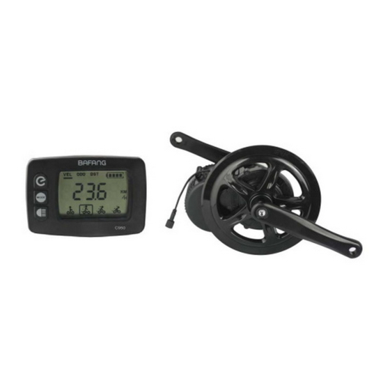
C950 Display 2.1 Material and waterproof grade Display’s casing use black/silver ABS materials, display window use acrylic white transparent material. Working temperature of display: - 20℃- 80℃. Waterproof grade: IP65. Ultrasonic is used for welding casing and display window. 2.2 Dimension (unit: mm) -
Page 16: Installation Instruction
2.3 Installation instruction Fix the display onto the handlebar and adjust to an appropriate visual angle, use a screw to fix the carrier onto bottom casing, then plug display connector with controller connectors, that’s all. Bottom casing cable Fixing slot Fixing carrier cable Fixing carrier... -
Page 17: Button Definition
2.4 Button definition C950 display is equipped with integrated buttons. The three buttons are installed on the left side. The shape and location is as below: System power switch ode selection, together with for setting back light switch, speed, mileage switch 2.5 Display Area Display area includes battery capacity, riding mode, riding speed, single riding distance, total riding distance, and malfunction code of... -
Page 18: Power On
Mode 1:walking assistant mode Mode 2:economic mode Mode 3:sports mode Mode 4:power mode 2.6 Power on First open the electric vehicle battery power. Then press to open system power(display below black font when power on)... -
Page 19: Adjust
press and choose favorite mode(refer to 2.7.1) 2.7 Adjustment 2.7.1 Mode selection When e-bike power on, default mode is economic mode, press 0.5s to select mode, economic mode, sports mode and powerful mode will be cyclic in order as following: economic mode sports mode power mode... - Page 20 2.7.2 Walking Assistant Hold to enter walking assistant mode. The e-bike will go on at a uniform speed below 6 KM/H. Release , the e-bike goes back to previous state, interface is as below: Walking assistant mode Warning: walking assistant function can only be used when the user is pushing the e-bike.
- Page 21 battery capacity is normal, the four battery segments lighten according to actual capacity. When the battery is under voltage, four battery segments switch off and battery display frame will flash with the frequency of 1 HZ, to remind user to recharge battery immediately. 2.7.5 Speed and mileage switch When power on, display shows the current speed automatically.
-
Page 22: Parameter Setting
total distance single riding distance 2.8 Parameter setting Parameter setting includes:wheel diameter setting(8inch~28inch) and battery voltage setting (24V、 36V). ( The display is set already, do not set it again except the user has special requirements.) Put the power on, hold together 3s to go the setting state,... - Page 23 accuracy. Wheel size includes 08、10、12、14、16、18、20、22、 26、28,choose in turn,interface is as below: “"1":wheel size setting mode "26":wheel size 2.8.2 Battery voltage setting Hold 0.5s to go to voltage setting interface, hold 0.5s to choose right voltage to make sure the display works normally. There are two options of 24V and 36V, choose it in turn, interface is as below: "2":voltage setting mode "36":battery voltage...
-
Page 24: Power Off
below: "3":riding distance reset 2.8.4 Exit the setting state In the state of parameter setting, hold for 3s to save the current settings and exit the setting interface. Attention: With no action for 5 seconds, it will exit the setting interface automatically, and the adjustment will not be saved. -
Page 25: Sensor
"11": Temperature sensor inside of controller has problem Note: The display can’t quit the malfunction code interface until the malfunction is solved. The e-bike can not work when it is in malfunction code display state. status data meaning 0x01 Normal condition 0x03 Have braked 0x04... - Page 26 0x23 light has problem 0x24 light sensor has problem 0x30 communication has problem 3 Speed detecting sensor By measuring the wheel RPM, the signal is transferred to the controller, the speed and mileage will be showed on the display. 3.1 Dimension 3.2 Installation 1.
- Page 27 2. Fix the speed sensor on appropriate position (bottom fork is suggested) of frame by ribbon. tied by ribbon 3. Fix the magnet on spoke of rear wheel Note: magnet's surface must be parallelized with sensor's surface 4. Adjust the distance between speed sensor and magnet within...
- Page 28 gap distance ≤ 5mm fix the nut after adjust appropriate position Connection diagram Battery Motor, a) Brake sensor controller, b) Brake sensor pedal sensor c) Display d) Throttle e) EB-BUS cable Battery g) Speed detecting sensor...
- Page 29 5 Notes 1.Should be stocked in a dry ventilated warehouse, do not be stocked in a humid, acidic and alkaline area, not coexist with magnetic object 2.Each connector inserted according to arrow to arrow 3.Avoid sharp objects impact on display 4.Avoid overload for long time when using 5.Avoid wading and soaking...
-
Page 30: Installation
Bafang technology service department who makes sure that if the products are under warranty or not. If it is under warranty, Bafang will offer repair or replacement for free. If it is out of warranty, Bafang still can... -
Page 31: Packing List
If this warranty statement is against to Chinese current law, the Chinese law shall prevail. Bafang reserves the right to modify the terms without any announcing in advance. 7 Packing list Two sets system per carton with packing list: 1.BBS01 motor...
Need help?
Do you have a question about the 8FUN and is the answer not in the manual?
Questions and answers