Table of Contents
Advertisement
Available languages
Available languages
Quick Links
.
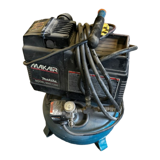
OWNERS MANUAL FOR
Permanently Lubricated Air Compressor
MODEL NO.
MAC1 200
SPECIFICATION CHART
NOTE:
IMPORTANT:
For identification
of
Parts, see Page 11 in this
Manual.
Carefully Before Operating.
Read the Safety Guidelines and All Instructions
Minimum Circuit Requirement 15 AMPS
+A circuit breaker is preferred. Use only
a
fuse or circuit breaker that is the same rating as the branch
circuit the air compressor is operated on. If the air compressor is connected to a circuit protected
by fuses, use time delay fuses.
I
Model No.
Horsepower
Displacement CFM
SCFM
G2
40 psig
SCFM
G2
9Opsig
Cut-In
cut-out
Bore
Stroke
Voltage-Single Phase
+
Fuse Type
Amperage at Max. Pressure
Tank Size
U.L. & CUL Listed
MAC? 200
,
;c*
2
11.9
8.3
6.1
100
PSI
125 PSI
2
38"
1.35"
120
15 amps
4 Gallon
"Fusetron" Type T
k
~
WMAC12QQA
Rev.
1/14/97
Advertisement
Table of Contents
Troubleshooting

Subscribe to Our Youtube Channel
Related Manuals for Makita MAC1200


Summary of Contents for Makita MAC1200
- Page 1 Permanently Lubricated Air Compressor Minimum Circuit Requirement 15 AMPS +A circuit breaker is preferred. Use only circuit the air compressor is operated on. If the air compressor is connected to a circuit protected by fuses, use time delay fuses. For identification Manual.
-
Page 2: Safety Guidelines
Inspection and Replacement Safety Valve Check Valve Replacement Motor STORAGE TROUBLESHOOTING GUIDE AIR COMPRESSOR DIAGRAM AIR COMPRESSOR PARTS LIST AIR COMPRESSOR PUMP DIAGRAM AIR COMPRESSOR PUMP PARTS LIST WARRANIY STATEMENT DEFINITIONS OR LOSS OF LIFE AWARNING THAT MIGHT CAUSE SERIOUS LOSS... -
Page 3: Important Safety Instructions
OF AIR TOOLS, spray guns, air operated accessories, tires INFLATABLES CAN CAUSE THEM TO EXPLODE or fly apart, and could result in serious injury. Your AIR COMPRESSOR is powered b) electricity. Like anv other electricallv powered-device,-&it is NOT USED RISK ELECTRIC... - Page 4 IMPORTANT SAFETY INSTRUCTIONS HAZARD RISK TO BREATHING RISK FROM FLYING OBJECTS . .. :.:.. " : : : . ::. RISK FROM MOVING PARTS RISK BURN WHAT CAN HAPPEN The COMPRESSED AIR from your NOT SAFE FOR compressor BREATHING! The air stream may contain carbon monoxide or other toxic vapors, or particles from the tank or other components.
-
Page 5: Description Of Operation
All Makita manufactured air compressors should be operated on not more than a 50% duty cycle. This means an air compressor that pumps air more than 50% of one hour is considered misuse, because the air compressor is undersized for the required air demand. -
Page 6: Grounding Instructions
INSTALLATION AND BREAK-IN PROCEDURES location the Air Compressor Locate the air compressor in a clean, dry and well ventilated area. The air filter must be kept clear of obstructions which could reduce air delivery of the air compressor. The air compressor should be located at least 12"... -
Page 7: Additional Regulators & Controls
If drain cockvalve is plugged, release all air pressure. The valve can then be removed, cleaned, then reinstalled. 10. After the water has been drained, close the drain cock or drain valve. The air compressor can now be stored. NOTE contain some closely followed. -
Page 8: Air Filter Inspection And Replacement
ROUTINE MAINTENANCE SCHEDULE Each Year of Operation or ifa Problem is Suspected: Check condition of air compressor pump intake and exhaust valves. make sure they are Check condition of check valve. Replace if damaged or worn necessary. -
Page 9: Troubleshooting Guide
Before you store the air compressor, make sure you do the following: 1. Review the “Maintenance” and ”Operating Procedures” sections and perform maintenance as necessary. Be sure to drain water from the air tank. TROUBLESHOOTING GUIDE PERFORMING REPAIRS MAY EXPOSE VOLTAGE SOURCES, MOVING PARTS OR COMPRESSED AIR SOURCES. -
Page 10: Troubleshooting Guide
TROUBLESHOOTING GUIDE (Continued) PROBLEM Knocking Noise Compressor is not supplying enough air to operate accesso- ries. Motor will not run. X..' '..,,':,[ Regulator knob has continuou! air leak. Regulator will not shu at air outlet. CORRECTION CAUSE Remove and clean, or replace. tefective check valve. -
Page 11: Air Compressor Diagram
AIR COMPRESSOR DIAGRAM TORQUE 95 to 105 Ibs. SNUG in. Ibs. - 24... - Page 12 PART NUMBER CAC-1080 AC-0046 SS-655-ZN CAC-1121 AC-0426 SSF-1001-1 SSP-7813 AC-0406 SSF-3156 TA-4405 AC-0261 SSP-7811 SS-8553 CAC-4290-3 AC-0249 ACG-18 _.,. :., ... 91 895680 ..SSF-953-ZN SSP-480 SST-5314-1 TIA-4150 SSW-7367 SSF-607 AGO1 73 CAC-4296-1 AC-0266 AC-0404 SUDL-403-1 SSP-6021 SSG-3105...
-
Page 13: Air Compressor Pump Diagram
AIR COMPRESSOR PUMP DIAGRAM 100 to 120 Lbs. 5 8 - 59uz> w7’ $ / 7 0... -
Page 14: Air Compressor Pump Parts List
AIR COMPRESSOR PUMP PARTS LIST PARTNUMBER AC-0252 SSF-589 SSF-927 ACG-45 *J 57 AC-0032 SSG-8156 Ma9045 AC-0140 SSF-615 AC-0108 ..SSF-586 ,:., ..SSF-3158-1 *J 70 . " *J 72 DAC-161 KK-4315 AGO281 Keys 57,59,60,61,70,71, and 72 are purchased as part of KK-4835 piston/cylinder kit. -
Page 15: Service Notes
SERVICE NOTES... - Page 16 OWNERS MANUAL FOR Permanently Lubricated Air Compressor ..:.., MODEL NO. MAC1 200...
- Page 17 MANUAL DEL OPERADOR PARA COMPRESOR DEAIRE DE LUBRICACION PERMANENT€ MAC1 200 TABLA DE ESPECIFICACIONES Modelo No Pot encia Desplazamiento CFM SCFM @ 40 psig SCFM @ 90 psig Presi6n de arranque Presion de code Orificio Carrera del piston Voltaje monofasico Tipo de fusible Amperaje a max.
-
Page 18: Pautas De Seguridad
PAUTASDE SEGURIDAD TmmDEADVERTENClAS GLOW10 ClCLO DElRABAJO I N F O R M A C I O N GENERAL I N SPECCI O N ALRECIBIR DESCRI P CI O N DE LAOPERACION INSTALACIONY PROCEDIMIENTOS PARAEL ASENTAMIENTO Ubicaci6n del Compresor de Aire : : . -
Page 19: Instrucciones Importantes De Seguridad
INSTRUCCIONES IMPORTANTES DE SEGURIDAD CONSERVAR ESTAS INSTRUCCIONES DEOPERACI~N NTES DE USAR ESTA UNIDAD. RIESGO bnque SIGUIENTES CONDICIONES PODRiAN conducir at debilitamiento COMO RIESGO DE EXPLOSION EXPLOSION DELTANQUE: 1. OMlTlR DRENAR APROPIADAMENTE EL AGUA condensada que oxidarli el tanque de acero, debilitindolo paredes. - Page 20 INSTRUCCIONES IMPORTANTES RIESGO RIESGO A LA RESPIRAUON RIESGO DE OBJECTOS PROPULSADOS RIESGO DE PIE= MOWBLES RIESGO QUEMADUW DE SEGURIDAD (Cont.) PUEDE SUCEDER AIRE COMPRIMIDO producido por la unidad iNO ES SEGURO PARA RESPIRAR! chorro de aire puede contener monoxido de carbono, otros vapores toxicos, particulas provenientes del tanque u ovos componentes.
- Page 21 PREsldN DE ARRANQUE Cuando el motor estA de aireva disminuyendo conforme usted continlia Ninglin compresor de aire fabricado por Makita debe operarse a que bombea aire durante mi& del de una b r a se considera que estA siendo mal usado poque el compresor de Are estd subdimensionado para la demanda.
-
Page 22: Descripcion De La Operacion
DESCRIPCION DE LA OPERACION Vdlvuia de Alivio de Presi6n: Lavdlvula de alivio de presiixl que se al lado encuentra del intemptor de presih, escapar aire comprimido del cabezal del compresor autmaticamente y del tubo de salida cuando el compresor de aire alcance la presi6n de “corte”... -
Page 23: Procedimientos Para Operar
INSTALACION Y PROCEDIMIENTOS PARA INSTRUCCIONES PARA CONECTAR ATIERRA (Cont.) Si se va a reparar reemplazar el cord& o enchufe, el alambre para tierra debe mantenerse separado de 10s alambres conductores de corriente. Nunca conectar alambre para tierra a una espiga plana del enchufe. -
Page 24: Mantenimiento
LA UNIDAD ENTRA EN FUNCIONAMIENTO AUTOMATICAMENTE CUANDO ESTA ACTIVADA EN"ON*-. AL HACERLE MANTENIMIENTO USTED PUEDE QUEDAR EXPUESTO A COMPRIMIDO. PUEDEN OCURRIR DAfiOS PERSONALES. ANTES DE INTENTAR HACER REPARACIONES 0 CUALQUIERTIPO MANTENIMIENTO, DESCONECTAR Para asegurar la operaci6n eficiente y una larga vida ljtil de la unidad compresora de aire, se debe preparar y seguir un programa de mantenimiento. - Page 25 Antes de guardar el compresor de aire, asegurarse de siguiente: Leer las secciones de ‘Mantenimiento” y <<Procedimiento para Operarn en las @ginas precedentes hacer el mantenimiento seglin fuese necesario. Drenar el agua del aire que se hubiese acumulado en el tanque de aire. GUIA PARA DIAGNOSTIC0 DE PROBLEMAS AL HACER EL MAMENIMIENTO PUEDEN QUEDAR EXPUESTAS LAS FUENTES DEVOLTAJE, PARTES MOWBLES 0 FUENTES DE AIRE COMPRIMIDO.
- Page 26 GUiA PARA DIAGNOSTIC0 DE PROBLEMAS PROBLEMA Sonido de golpes. compresor no provee suficiente aire para operar 10s accesorios. motor funciona. ‘’ , . < ..,... ‘ : I .:..x....,. ; . ( . -.
- Page 27 DIAGRAMA DEL COMPRESOR DE AlRE NUMERO TORQUE EN DIAG. 95 a 105 Pulg. Lb. AJUSTAR Pulg. Lb.
- Page 28 LISTA DE PARTES DEL COMPRESOR NUMERO EN DlAGRAMA -..1 6..:: " L : , . :,..::I .., : ..NUMERO DE PARTE CAC-1080 BANDEJA PARA HERRAMIENTAS POSTERIOR AGO046 CUBIERTA...
- Page 29 -DIAGRAMA DE LA BOMBA DEL COMPRESOR DE AlRE NUMERO EN DIAG. TORQUE 100 a 120 Pulg. Lb. 100 a 120 Pulg. Lb. 120 Pula. Lb. 120 Pulg. Lb. a 60 Pulg. Lb. Pulg. ,i” -bbsmdeawwd6ndeM- q1edu”oext~delabrruest6dm extern. rodamlento. con I s parte COLOCAR CON LA MARCA DE BICAC~NAWNTAND~ HACIA...
- Page 30 LISTA DE PARTES DEL COMPRESOR DE AlRE NUMERO NUMERO MAGRAMA PARTE AGO252 SSF-589 SSF-927 ACG-45 AGO032 ‘ 4 5 9 SSG-8156 ‘ 6 0 ‘461 MO-9045 AGO1 40 SSF-615 AGO1 08 SSF-586 ‘J70 SSF-3158-1 :.:.I ..i:. “ .:> ..% . I ’...
- Page 31 NOTAS...
- Page 32 ( U dovobr k a henamienta COMPLETA con llsto ta inrpeccib, M i i . q u e elpmblsma a i g w c a p Makita. ta Wdodo de 9Omnti. del tirmina de un de M .
- Page 33 G U I D E D DU COMPRESSEUR D'AlRA LUBRIFICATION PERMANENT€ TABLEAU DES SPECIFICATIONS Modele No : Puissance en c.-v. Cylindre (p Wmin) pP/min standard pP/min standard Enclenchement Coupecircuit A l b g e Course du cylindre Tension-phase simple Genre de fusible lntensite a pression max.
-
Page 34: Mesures De Securite
MESURESDE SECURI~ TABLEAU DE MISESEN GARDE m Q U E FACTEUR D'UTILISATION RENSEIGNEMENTSGENERX INSPECTION SURRECEPTION DESCRIPTION DU MODE OPERATIONNEL PROCEDURESD'INSTALIATION EN ROUTE Emplacement du compresseur d'air ..:;! Lubrification huile 4 : ..I Rallonges Tubages Directives de mise... -
Page 35: Mesures De Securite Importantes
MESURES DE SECURITE IMPORTANTES GRAVES BLESSURES ET DES DOMMAGES A LA LES MISES EN GARDE ET LES INSTRUCTIONS SUR LE FONCTIONNEMENT AVANT D'UTILISER CE PRODUIT. DANGER f6sewoir d ' a i r CONDITIONS SUIVANTES POURRAIENT ENTRAINER I'affaiblissement, du reservoir et RISQUE D' E CLATEMENT CAUSER CMPLOSION AVEC REACnON VIOLENTE. - Page 36 MESURES DE SECURITE IMPORTANTES DANGER RISQUE DE PROJECnON D'OBJETS . : : , RISQUE CAUSE PAR LE! PIECES MOBILES BROLURES RISQUE DE RISQUE LAIR COMPRIME de votre compresseur "EST PAS SECURITAIRE POUR CINHALATION Le debit d'air peut contenir du monoxyde de carbone et d'autres vapeurs toxiques o u particules provenant du reservoir ou autres co m posa nts...
-
Page 37: Facteur D'utilisation
FACTEUR D'UTILISATION TOUS les compresseurs d'air fabriquk par Makita doivent fonctionner ou compresseur qui pompe de I'air pendant plus de une demie heure en une heure ( 50 % de une heure) est considere comme etant mal utilise, compresseur 6tant trop petit pour la demande d'air exigee. - Page 38 DESCRIPTION DU MODE OPERATIONNEL (suite) Wtendeur de pression : Le detendeur de pression, situe sur le c8te du manostat, est conGu pour liberer automatiquement I'air comprime delatBteducompresseur etdu tuyaude sortie lorsquelecompresseur atteint la'pression dscoupe-circuit" ou qu'il est feme. Si I'air n'est pas libere, le moteur essaie de demarrer mais en est incapable.
- Page 39 -INSTALLATION ET PROCEDURES DE MISE EN ROUTE- DIRECTIVES DE MISE A LA TERRE Lors de la reparation ou du remplacement du cordon ou de la fiche, le fil de terredoit 6tregard6 s6parhentdesfils potteursd'electricite. Ne branchez jamais fil de terre unefiche avec lame de contact plate. Lefildeterre est recouvertd'unegaineisolantedont lasurface exteme est verte avec ou sans rayures jaunes.
-
Page 40: Directives D'entretien
MET AUTOMATIQUEMENT EN MARCHE LORSQU'IL EST ALLUME. AU COURS DE CENTRETIEN, IL CAPPAREIL SE PEUT SOYEZ =POSE AUX SOURCES QUEVOUS RISQUANT AlNSl DES BLESSURES. DEBRANCHEZ L'APPAREIL RESERVOIR D'AIR AVANT D'ENTAMER TOUT ENTRETIEN OU TOUTE REPARATION. Afin d'assurer rendement efficace et une duree de vie utile plus longue du compresseur prepare observe. -
Page 41: Guide De Depannage
Avantd'entreposer lecompresseur d'air, assurez-vous desuivre les etapes suivantes Consultez noweau les sections portant sur I'entretien procdures operationnelles et effectuez sont nkessaires. Assurez-vous de purger l'eau du reservoir d' a ir. GUIDE DE DEPANNAGE DESREPARATIONS PEUVENTVOUS EXPOSER AUXSOURCESDETENSION, AUX PlkCESMOBlLESOU AUXSOURCES D'AIR COMPRIME. - Page 42 GUIDE DE DEPANNAGE (Suite) PROBLEME Cognements. Le compresseur ne fournit pas assez d'air pour utiliser des accessoires. Le moteur ne toume pas..:: '.,, Fuite &air continue au bouton d r6gulateur. Le r6gulateur ne coup la sortie dair. CAUSE joupape de retenue defectueuse.
- Page 43 DIAGRAMME DU COMPRESSEUR D'AIR C& COUPLE 95 a 105 livres-pouce ERGOT 50 a 60 livres-pouce...
- Page 44 LlSTE DES PIECES DU COMPRESSEUR D'AIR PIECES CLE NQ CAC-1080 AGO046 SS-&ZN CAC-1121 AGO426 SSF-1001-1 SSP-7813 AG0406 SSF-3156 TA-4374 AGO261 SSP-7811 ss-8553 CAC-429@-3 . .. AGO249 ' : ; ! A C G - I 91 895680 SSF-953-ZN SSP-480 SST-5314-1 TIA-4150 ssw-7367 SSF-607...
- Page 45 -DIAGRAMME DE COUPLE 100 a 120 livres-pouce 120 livres-pouce 120 livres-pouce 60 livres-pouce 48 livres-pouce POMPE DU COMPRESSEUR D'AIR- 5g-0 $ / 7 0 .
- Page 46 LISTE DES PIECES DE LA POMPE CLE NQ : PIECES N*-: AGO252 SSF-589 SSF-927 ACG-45 AC-0032 SSG-8156 * 6 0 MO-9045 AGO1 SSF-615 AC-0108 SSF-586 SSF-3158-1 DAG1 61 KK-4315 AGO281 Les des 57,59,60,61,70,71 et 72 ne peuvent &re achetees que comme pikes faisant partie de la trousse pistodcylindre KK-4835.
- Page 47 NOTES D'ENTRETIEN...
- Page 48 =&wires. e 4 done possible ne pumdlenl paa limilalion sur la durh de la garanlie implicile nkessairsma 1 vow. MODEL DE MAKITA Garantie d'une v k i i a l i o n complble el tmai avant quillr la manufaclure.
Need help?
Do you have a question about the MAC1200 and is the answer not in the manual?
Questions and answers