EVS XTnano Technical Reference
Video & media server
Hide thumbs
Also See for XTnano:
- Hardware technical reference manual (70 pages) ,
- Configuration manual (62 pages) ,
- Operation manual (102 pages)
Table of Contents
Advertisement
Advertisement
Table of Contents

Related Manuals for EVS XTnano


![Server EVS XT[2] Technical Reference Hardware Manual](https://static-data2.manualslib.com/product-images/0f2/946555/60x60/evs-xt-2-server.jpg)


Summary of Contents for EVS XTnano
- Page 1 TECHNICAL REFERENCE HARDWARE Version 11.01 - January 2013...
- Page 3 (for manuals on hardware products) or at the following page on the EVS website: http://www.evs.com/contacts. User Manuals on EVS Website The latest version of the user manual, if any, and other user manuals on EVS products can be found on the EVS download center, on the following webpage: http://www.evs.com/downloadcenter.
- Page 4 EVS Broadcast Equipment S.A. - January 2013...
-
Page 5: Table Of Contents
XTnano Server - Version 11.01 - Hardware Technical Reference Manual Table of Contents TABLE OF CONTENTS WHAT'S NEW? 1. OVERVIEW 1.1. Presentation 2. SAFETY AND COMPLIANCE 2.1. Safety 2.2. EMC Standards 2.3. EMC Warning 2.4. FCC Marking 2.5. CE Marking 3. HARDWARE SPECIFICATIONS 3.1. - Page 6 EVS Broadcast Equipment S.A. - January 2013 Issue 11.01.C 5.3. Video Connections 5.4. Audio Connections 5.4.1. Audio Channels 5.4.2. Digital Audio DA-15 Pinout 5.4.3. Analog Audio DA-15 Pinout 5.4.4. Monitoring Audio DA-15 Pinout 5.5. RS422 Connections 5.5.1. RS422 Connector Pinout 5.6.
-
Page 7: What's New
XTnano Server - Version 11.01 - Hardware Technical Reference Manual What's New? The new features added on release 11.01 do not have an impact on the hardware technical reference manual of this EVS server. The manual has however been subject to slight changes to reflect the current situation:... - Page 8 EVS Broadcast Equipment S.A. - January 2013 What's New?
-
Page 9: Overview
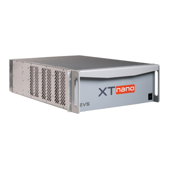
Overview 1.1. Presentation Welcome to the EVS range of products and thank you for using an EVS XTnano server. We will do our best to satisfy your video production needs and we look forward to continuing working with you. The EVS XTnano servers are full digital in PAL (625i), NTSC (525i), 720p, and 1080i standards. -
Page 10: Safety And Compliance
EVS Broadcast Equipment S.A. - January 2013 Issue 11.01.C Safety and Compliance 2.1. Safety This equipment has been designed and tested to meet the requirements of the following: • EN 60950 (European): Safety of information technology equipment including business equipment. -
Page 11: Emc Warning
XTnano Server - Version 11.01 - Hardware Technical Reference Manual Standard Area Title EN 61000-4-7 European European Electromagnetic Compatibility (EMC) Part 4 (Limits), Section 7; harmonics and interharmonics measurements and instrumentation, for power supply systems and equipment connected thereto. EN 61000-4-11 European European Electromagnetic Compatibility (EMC) Part 4 (Limits);... -
Page 12: Fcc Marking
EVS Broadcast Equipment S.A. - January 2013 Issue 11.01.C 2.4. FCC Marking This equipment has been tested and found to comply with the limits for a Class B digital device, pursuant to Part 15 of the FCC Rules. These limits are designed to provide reasonable protection against harmful interference in a residential installation. -
Page 13: Hardware Specifications
3.1.1. Rack Mount 4U Main Frame Weight 4U - 19 inches chassis 30 kg / 66.15 lb Dimensions The following drawings provide the various dimensions, in mm, of the XTnano server with a 4U chassis. Front view Left view 3. Hardware Specifications... - Page 14 EVS Broadcast Equipment S.A. - January 2013 Issue 11.01.C Right view Top view 3. Hardware Specifications...
-
Page 15: Control Devices
XTnano Server - Version 11.01 - Hardware Technical Reference Manual 3.1.2. Control Devices The following control devices can optionally be connected to your server to control it. Nano Remote Control Panel Weight: 3.4 kg / 7.5 lb. Keyboard Weight: 0.4 kg / 0.9 lb. -
Page 16: Power Supply
EVS Broadcast Equipment S.A. - January 2013 Issue 11.01.C 3.2. Power Supply Redundant Power Supply The server is fitted with two auto switching and hot-swappable power supplies. The secondary hot-swappable power supply should be connected to the mains to allow automatic power switching to this second power supply should the first one fail. - Page 17 XTnano Server - Version 11.01 - Hardware Technical Reference Manual Storage and Transport • Temperature: 0°C to +70°C (32°F to 158°F) • Relative humidity: 0% to 90% (non-condensing) 3. Hardware Specifications...
-
Page 18: Software Specifications
EVS Broadcast Equipment S.A. - January 2013 Issue 11.01.C Software Specifications 4.1. Video Specifications Video Standards The following table lists the video specifications both in SD and in HD format for your XTnano server. Standard Definition High Definition Video Formats 525i 59.94fps (NTSC) -
Page 19: Audio Specifications
XTnano Server - Version 11.01 - Hardware Technical Reference Manual SMPTE Standards The following table lists the SMPTE standards supported by your server. Configuration SMPTE standard SD SDI ST 259:2008 (525i 59.94 Hz; 625i 50 Hz) HD SDI ST 292-1:2011, ST 292:2012 (720p 50 and 59.94 Hz; 1080i 50 and 59.94 Hz) -
Page 20: Video Codecs And Bitrates
• Audio mix 4.3. Video Codecs and Bitrates 4.3.1. Supported Codecs Codecs and Related License Codes The XTnano server uses an intra-frame video encoding technique. It supports natively the following video codecs: Codec Code Protection DVCPro 50 √ Code 9 DVCPro HD √... -
Page 21: Maximum Bitrates
1-line shift of the field, resulting in a vertical jitter of the picture. The jitter frequency depends upon the chosen playback speed. To avoid this phenomenon and provide a stable output picture, EVS developed 2 types of line interpolator: 2-line and 4-line interpolators. The interpolation process can be enabled or disabled by the operator on all EVS slow motion systems. - Page 22 The interpolator is of course always disabled at 100% playback speed, because there is no parity violation. EVS uses the same techniques with the Super Slow Motion disk recorder, working with all models of Super Motion cameras (150/180 Hz). The only difference between the...
-
Page 23: Recording Capacities
XTnano Server - Version 11.01 - Hardware Technical Reference Manual 4.4. Recording Capacities Disk Storage The maximum internal disk storage available on SAS disks, is as follows: • 6 (5+1) x 300 GB SAS disks Raid Level: 3 The Video Raid uses striping process across 5 or 6 disk drives. The video and audio data is striped over the first 4 or 5 drives while the parity information is saved on the fifth or sixth drive. -
Page 24: Hardware Installation And Cabling
Check thanks to the included packing list if all the items are present and if they show any mechanical damage. If yes, report damage or the missing parts to EVS or their appropriate representative. 5.1.2. -
Page 25: Rear Panel Description
5.2.2. 4U Rear Panel Layout Rear Panel Areas The following drawing represents an example of a 4U rear panel available on an XTnano server. The various areas of the rear panel are highlighted in the drawing and their respective variants are listed in the following table along with a short description of the related connectors. - Page 26 EVS Broadcast Equipment S.A. - January 2013 Issue 11.01.C Video and Codecs The codecs modules allow connections for recording and playback of video material. Each connector on a codec module is connected to the corresponding J connector on the COD A or COD B module of a V3X board.
- Page 27 XTnano Server - Version 11.01 - Hardware Technical Reference Manual Analog Audio The analog audio inputs and outputs are available on multi-pin (DA-15) connectors for audio signal inputs and outputs in analog format. See section "Audio Connections" on page 21 for more details on the DA-15 connectors pinout according to the different configurations.
-
Page 28: Power Supplies
The Timecode connectors allow the server to receive or send back the LTC timecode reference signal. • The Gigabit Ethernet connectors allow the interconnection of servers, other EVS, and/or third-party systems into a Gigabit Ethernet network. • The Multiviewer connector provides an analog Multiviewer output on a DA-15 connectors, that can be configured in CVBS, RGB HD or YUV HD. -
Page 29: Video Connections
Audio Connections 5.4.1. Audio Channels The XTnano server manages up to 64 embedded audio channels, depending on the chosen variant and the installed hardware. The embedded audio modules and codecs can be used as input or output channels for embedded, digital (AES/EBU), or analog audio signals. -
Page 30: Digital Audio Da-15 Pinout
EVS Broadcast Equipment S.A. - January 2013 Issue 11.01.C 5.4.2. Digital Audio DA-15 Pinout The digital audio DA-15 connector is illustrated hereunder (connector installed on the rear panel and viewed from outside). Its pinout is described in the following table where each column corresponds to one of the 4 available connectors. -
Page 31: Analog Audio Da-15 Pinout
XTnano Server - Version 11.01 - Hardware Technical Reference Manual 5.4.3. Analog Audio DA-15 Pinout The analog audio DA-15 connector is illustrated hereunder (connector installed on the rear panel and viewed from outside). Its pinout is described in the following table where each column corresponds to one of the 4 available connectors. -
Page 32: Monitoring Audio Da-15 Pinout
EVS Broadcast Equipment S.A. - January 2013 Issue 11.01.C 5.4.4. Monitoring Audio DA-15 Pinout The monitoring audio DA-15 connector is illustrated hereunder (connector installed on the rear panel and viewed from outside). Its pinout is described in the following table. -
Page 33: Rs422 Connections
RS422 Connections 5.5.1. RS422 Connector Pinout The RS422 connectors are used to connect a remote control (from EVS or third party) to your server. The cable wiring is a straightforward pin-to-pin connection as illustrated in the following diagram. You should use a shielded cable to avoid electromagnetic interference on long distances. -
Page 34: Gigabit Network
A non-linear editing system, such as Apple Final Cut Pro. However, the external systems cannot read the raw files coming from a XTnano server. For this reason, XTAccess is used as a “gateway” between your server and the IT world. -
Page 35: Important Rules
10G uplinks are required, but no inter-VLAN routing is needed. On larger setups, both GigE ports of the XTnano servers or/and several ports on the SANs are often used to increase the bandwidth or to allow redundancy. Since both GigE ports of an XTnano server cannot be used on the same sub-network, virtual LANs need to be created. -
Page 36: Additional Information
EVS Broadcast Equipment S.A. - January 2013 Issue 11.01.C Stack- Dual Model/Product Number Uplinks rout- ports switching HP Procurve 2510G-24 4x1G SFP (+4) Cisco Catalyst WS-C2960S- 2x10GIG 24TD-L SFP+ or 2x1G SFP Cisco Catalyst WS-C2960S- 2x10GIG 48TD-L SFP+ or 2x1G SFP... -
Page 37: Gpio Connections
5.7.2. GP In Connections GPI Triggers The allocation of the XTnano server GPI triggers is performed in the Multicam Configuration window, in the GPI tab. See the Configuration manual for detailed information on allocating GPI triggers. 5. Hardware Installation and Cabling... -
Page 38: Specifications
EVS Broadcast Equipment S.A. - January 2013 Issue 11.01.C Opto isolated Inputs (GP In 1, 2, 3, 4) Pin-Out Specifications • The input consists in an opto diode (VF @ 1.1 Volt) in series with a 470 ohm resistor. •... - Page 39 XTnano Server - Version 11.01 - Hardware Technical Reference Manual TTL Inputs (GP In 5, 6, 7, 8) Relay Inputs Pin-Out The relay must be connected between the ground and the corresponding TTL input on the DB-25. TTL Inputs Pin-Out Each TTL input on the DB-25 is directly connected to the pin of the TTL connector on the device triggering the GPI.
-
Page 40: Gp Out Connections
EVS Broadcast Equipment S.A. - January 2013 Issue 11.01.C 5.7.3. GP Out Connections Relay Isolated Outputs (GP Out 1, 2, 3, 4) Pin-Out The user can define the functions, types and settings associated to the GPI outs in the following applications: •... - Page 41 XTnano Server - Version 11.01 - Hardware Technical Reference Manual Specifications • each pin can be individually configured as an output or an input • internal 4K7 pull up to +5 V • low level Vi < 1.5 Volt (U12 = 74HC245) • high level Vi > 3.5 Volt (U12 = 74HC245) •...
-
Page 42: Boards Description
Issue 11.01.C Boards Description 6.1. Boards and Slots Configuration The XTnano server is equipped with several boards that are all developed by EVS. According to your server version, the following setup configurations are available: 4U Rack Installed boards Slot #... -
Page 43: V3X Video And Reference Boards
Warning It is highly advised not to remove a V3X board from your EVS server. Should you have to do so, manipulate the board very carefully, making sure it is not exposed to mechanical or electric shocks. -
Page 44: Block Diagram
EVS Broadcast Equipment S.A. - January 2013 Issue 11.01.C Block Diagram The block diagram of the V3X board is illustrated hereunder with the connectors, jumpers and LEDs location: 6. Boards Description... - Page 45 XTnano Server - Version 11.01 - Hardware Technical Reference Manual Base Board Jumpers The following table lists the V3X base board jumpers and their respective function: Jumper Function ST1, ST2 These 2 jumpers must be installed on the last V3X board of the server (that is on V3X #1, 2 if there are respectively 1, 2 V3X boards installed in the server).
-
Page 46: Cod Connectivity In Sd And Hd
EVS Broadcast Equipment S.A. - January 2013 Issue 11.01.C V3X COD Modules LEDs The following table lists the LEDs available on then V3X COD modules (from left to right): Color Status Function Green Blinking Indicates CPU activity. There is a problem with the module processor. -
Page 47: Connector Assignments
XTnano Server - Version 11.01 - Hardware Technical Reference Manual Connector Assignments Con- Con- SD mode HD mode nector nector label J5 is factory-wired to the backplane instead of J1. You can CHAR SD connect J1 instead of J5 if CVBS monitoring is required in SD or HD mode. - Page 48 EVS Broadcast Equipment S.A. - January 2013 Issue 11.01.C Connectors Positions and Assignments 6. Boards Description...
-
Page 49: Cod Connectivity In 3D Dual Link
XTnano Server - Version 11.01 - Hardware Technical Reference Manual 6.2.3. COD Connectivity in 3D Dual Link This section describes the connector assignments and layout for the video standards HD 3D in Dual Link mode. Connector Assignments Connector 3D mode Connector label CHAR SD SDI monitoring output Not wired to the backplane. -
Page 50: Channel Assignment
EVS Broadcast Equipment S.A. - January 2013 Issue 11.01.C Connectors Positions and Assignments 6.2.4. Channel Assignment 4 Channels Server Upper Codec (SLOT 3) Lower Codec (SLOT 2) 6. Boards Description... - Page 51 XTnano Server - Version 11.01 - Hardware Technical Reference Manual 2 Channels Server Lower Codec (SLOT 2) 6. Boards Description...
-
Page 52: Audio Codec Board
EVS Broadcast Equipment S.A. - January 2013 Issue 11.01.C 6.3. Audio Codec Board The audio codec board is the audio interface between the V3X boards and the H3X board. Video codec and audio codec boards are tied to the H3X board with one bus connector on the front side. -
Page 53: H3X Board
XTnano Server - Version 11.01 - Hardware Technical Reference Manual 6.4. H3X Board The H3X board is divided in 4 parts (2 in front, 2 in the back). • Front left: GBE (GigE) module. • Front right: CTL controller module. • Back left: CPU module . - Page 54 EVS Broadcast Equipment S.A. - January 2013 Issue 11.01.C LEDs Function The available LEDs on the XNet2CTL controller module are, from left to right: Color Status Function LED 1 Green An error occurred while booting the H3X board. LED 2 to —...
-
Page 55: Raid Controller Boards
XTnano Server - Version 11.01 - Hardware Technical Reference Manual 6.5. RAID Controller Boards 6.5.1. RCTL Board on SAS Disk Array Disk Arrays on systems with H3X boards have a controller on the disk array board. Different configurations can be used •... -
Page 56: Mtpc A3/A6 Board
EVS Broadcast Equipment S.A. - January 2013 Issue 11.01.C 6.6. MTPC A3/A6 Board Introduction The function of the PC board is mainly the control of the video hardware and the interface of the peripheral equipment (such as a remote controller) with the video hardware. - Page 57 • IDE System Hard disk: the IDE disk drive is used for storing the EVS software and the DOS operating system. Neither audio nor video data is saved on this disk. The capacity of this drive may vary depending on market availability, but the system partition is always set to 1 GB.
-
Page 58: Led Information
The ENVS jumper can be used to enable or not the presence of the VGA VS signal (Vertical Sync) in the composite output signal (TV mode) If the LSM TV mode is used, these jumpers must be set up according to EVS recommendations, which depend on software version and CPU board model/revision: Set up the jumpers as follows: •... - Page 59 This jumper should be removed if the device connected to the RS422 port is NOT an EVS controller. Maximum voltage on pin 5 of an RS422 port of the server should not exceed 5 Volt when the corresponding jumper is engaged. Applying a higher voltage on pin 5 when the corresponding jumper is engaged will result in permanent electronic damage to the board.
- Page 60 Belgium www.evs.com/contact EVS Broadcast Equipment is continuously adapting and improving its products in accordance with the ever changing requirements of the Broadcast Industry. The data contained herein is therefore subject to change without prior notice. Companies and product names are To learn more about EVS go to www.evs.com...
Need help?
Do you have a question about the XTnano and is the answer not in the manual?
Questions and answers