Table of Contents
Advertisement
Advertisement
Table of Contents

Subscribe to Our Youtube Channel
Related Manuals for McQuay FCVC

Summary of Contents for McQuay FCVC
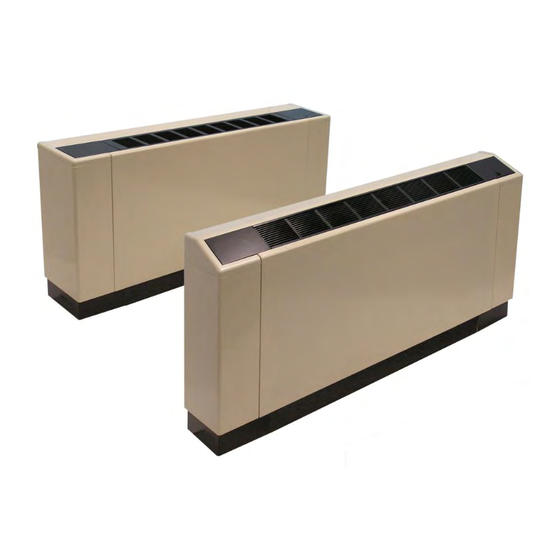
- Page 1 IM 980-1 Group: Applied Air Systems ThinLine 3G Vertical Fan Coils Part Number: 910102984 Type FCVC, FCVH, FCVS and FCWC Vertical Design Date: May 2011 200 to 1200 cfm IM 980-1 Model FCVC Model FCVS © 2011 McQuay International...
-
Page 2: Table Of Contents
Procedure ......... . .79 McQuay IM 980-1... -
Page 3: General Information
Optional Secondary Drain Pan Easily Removed Drain Pan & Motor Assembly (Supplied with Piping Packages) • For easy maintenance and service • Noncorrosive • Sloped, polymer drain pan for good IAQ • Easily removed McQuay IM 980-1... -
Page 4: Receiving And Storage
Check the packing list and unit identification/tagging numbers against the plans to verify that the unit is being McQuay IM 980-1... -
Page 5: Recommended Maintenance Clearance
A one-inch duct collar is provided on units with a ducted accept other types of conductors. Failure to do so may cause damage to the equipment. return and/or discharge to attach ductwork. McQuay recommends using galvanized sheet metal ductwork. Slide the WARNING sheetmetal duct over the duct collar flange of the unit, seal the joint and fasten with sheetmetal screws. -
Page 6: Installation
WARNING For hideaway units, if you are using McQuay’s Installation and maintenance are to be performed by qualified personnel who are familiar with local codes and Regulations, decorative wallplate, use blocks or other suitable and experienced with this type of equipment.. -
Page 7: Water Piping Connections
Install control valves so there is at least 2" (51mm) insulation, also damage to valves, wiring, electronics, minimum clearance to remove the actuator from the sensors, etc. See Figure 7. When McQuay provides valve valve body. McQuay IM 980-1... -
Page 8: Connecting To A Factory-Installed Valve & Piping Package
Push the main drain pan condensate hose back inside the • McQuay Deluxe and Enhanced piping packages include a end plate to prevent it from getting burned when making strainer which prevents debris from entering the coil. Clean sweat connections. -
Page 9: Condensate Drain Connection
Make piping connections to the steam coil per job requirements. (McQuay does not supply steam piping connections.) Install a 1/2", 15-degree swing check vacuum breaker in the unused condensate return trapping as close as possible to the coil.The following procedures are... -
Page 10: Two-Pipe Systems With Electric Heat
If used for auxiliary intermediate season Low-voltage heating, additional control is required. A second switch or pipe conductors sensor is required. Contact your McQuay representative for brought in here more information. To protect the electric heat elements, an automatic and manual electric heat switch disengages the electric heat to prevent overheating. -
Page 11: Thermostat And Controls
V wire must then be capped off with a wire nut or male terminal as appropriate. Please refer to the unit wiring diagram. Mains Operating Voltages Flexible Hose Operating voltages are as follows (+/– 10%). • 115/60/1 • 208-230/60/1 • 265-277/60/1 McQuay IM 980-1... -
Page 12: Operating Limits
IMPORTANT It is McQuay’s policy not to make recommendations on water treatment. It is the responsibility of the user to check that the water supply to the units is free of contaminants or corrosive agents, chemicals or minerals. -
Page 13: Operation And Maintenance
(see Fresh Air Damper‚ page 16). McQuay publication ED 18513-1 and ED 18527. • High, Medium, Low: Fan runs continuously at the selected speed. The two-position, motorized fresh-air damper, when MT155 Thermostat supplied, is opened. - Page 14 For more details refer to page 51, 55 or 59. Series MT158 and MT168 microprocessor-based thermostat-controllers combine a proportional integral control algorithm with adaptive logic. They may be unit-mounted or remote-wall mounted. Figure 16: MT158 and MT168 Thermostats McQuay IM 980-1...
-
Page 15: Low-Voltage (Lv) Interface Board
Figure 37, page 28 or the unit’s wiring diagram, which is mounted) McQuay thermostat or control. It can also be used in attached to the corner panel on cabinet units and to the chassis conjunction with a controller of a building automation system front cover on hideaway units. -
Page 16: Operation And Maintenance
Figure 22: Condensate Overflow Switch Installation Cold Weather Operation Unit heaters may experience erratic operation during cold ambient conditions with the outside air damper in the open position. McQuay IM 980-1... -
Page 17: Leveling Legs Option
Note: The need to reset the manual switch may indicate that there are improperly functioning system components. If Loosen the locking nut on the leveling leg bolt with a the switch trips again, contact McQuay Factory Service 9/16-inch wrench. for help in diagnosing the cause. -
Page 18: Key-Lock Access Door Kit
(this is opposite the side where the control access until the front edge of the filter drops down. panel is located on units with unit-mounted controls. See Figure 5, page 6 for a description of how to remove it. McQuay IM 980-1... - Page 19 Note: Push the tabs inward on the sides of the plug to free out of the unit. it from the connector base. The main condensate drain pan sits atop the fan deck and is now easily accessed for cleaning. To reinstall, follow these steps in reverse order. McQuay IM 980-1...
-
Page 20: Physical Data
152 (69) 177 (80) 202 (92) FCVH 55 (25) 63 (29) 74 (34) 91 (41) 110 (50) 129 (59) 149 (68) Note: *Approximate shipping weights do not include valve packages, hot water coils, electric heaters or other options. McQuay IM 980-1... -
Page 21: Unit Dimensions
18.7 18.7 18.7 Preheat Coil - Water Return Preheat Coil - Water Supply 23.2 23.2 23.2 23.2 23.2 23.2 23.2 Reheat Coil - Water Return 20.3 20.3 20.3 20.3 20.3 20.3 20.3 Reheat Coil - Water Supply McQuay IM 980-1... - Page 22 18.7 18.7 18.7 Preheat Coil - Water Return Preheat Coil - Water Supply 23.2 23.2 23.2 23.2 23.2 23.2 23.2 Reheat Coil - Water Return 20.3 20.3 20.3 20.3 20.3 20.3 20.3 Reheat Coil - Water Supply McQuay IM 980-1...
- Page 23 18.7 18.7 18.7 Preheat Coil - Water Return Preheat Coil - Water Supply 23.2 23.2 23.2 23.2 23.2 23.2 23.2 Reheat Coil - Water Return 20.3 20.3 20.3 20.3 20.3 20.3 20.3 Reheat Coil - Water Supply McQuay IM 980-1...
- Page 24 18.7 18.7 18.7 Preheat Coil - Water Return Preheat Coil - Water Supply 23.2 23.2 23.2 23.2 23.2 23.2 23.2 Reheat Coil - Water Return 20.3 20.3 20.3 20.3 20.3 20.3 20.3 Reheat Coil - Water Supply McQuay IM 980-1...
-
Page 25: Factory-Installed Valve & Piping Packages
Return distances are the same. Distances to connections from chassis are from unit mounting holes. Dimensions may vary slightly from given values. 2” [51 mm] 6.4” [163 mm] 4.2” 1.3” [33 mm] [107 mm] 4.9” [125 mm] McQuay IM 980-1... -
Page 26: Wiring Diagrams
Wiring Diagrams Wiring Diagrams Figure 35: Fan Coil Wiring Diagram - Typical with solid-state thermostat Note: All field installed conductors should have an insulation rating of 300 volts or greater. McQuay IM 980-1... - Page 27 Wiring Diagrams Figure 36: Fan Coil Wiring Diagram - Typical with unit-mounted three-speed fan switch Note: All field installed conductors should have an insulation rating of 300 volts or greater. McQuay IM 980-1...
- Page 28 Wiring Diagrams Figure 37: Fan Coil Wiring Diagram - Typical with electric heat and low-voltage interface board Note: All field installed conductors should have an insulation rating of 300 volts or greater. McQuay IM 980-1...
-
Page 29: Model Number Description
Preheat Coil Connection Type Primary Coil Type • S = sweated • C = chilled water only • T = threaded • W = CW/HW 2-pipe • N = none • H = hot water only • S = steam McQuay IM 980-1... - Page 30 • 040 = 4.0 kW Electric Heat • D = digital • 050 = 5.0 kW Electric Heat • R = DDC Ready • 060 = 6.0 kW Electric Heat • X = Special • 000 = None • Y = None McQuay IM 980-1...
- Page 31 • See Table 4 • X = special Valve - Preheat Coil Occ / Vacant Control Input • See Table 4 • Y = None Valve - Reheat Coil • X = special • See Table 4 McQuay IM 980-1...
- Page 32 • 04 = 4 Inch Extended Depth • XX = special • 08 = 08 inch Extended Depth Filter Unit Lineup Position • 1 = 1” Throwaway Filter • S = Standalone • 3 = 1” Throwaway + (1) Extra McQuay IM 980-1...
- Page 33 • Y = none from shipment or 60 month from installation) Packaging • X = special • S = Standard Product Style • T = palletized based on tagging and by floor • 1 = Style 1 McQuay IM 980-1...
- Page 34 This page intentionally left blank. McQuay IM 980-1...
-
Page 35: Im 1121 - Hideaway Unit Discharge Conversion Kit
The appropriate conversion kits are screws (see Figure available from McQuay for field installation. Contact your Attach the short front panel to the front of the chassis as McQuay Sales Represetative for details. shown. Secure the short panel with four of the retained... - Page 36 Figure 1: Removing the Discharge Duct Collar and Front Block-off Plate Discharge Duct Collar Front Block-Off Plate Figure 2: Attaching the Top Block-Off Plate and Short Front Panel Top Block-Off Plate Short Front Panel McQuay IM 1121...
-
Page 37: Im 1023 - Fresh Air Damper Kit
(see Figure Figure 3: Secure Damper with Tabs in Unit Base Pan Bend tabs in base pan over damper edge to secure in place. Page 37 © 2009 McQuay International 800-432-1342 www.mcquay.com... -
Page 38: Operation
It is the responsibility of the contractor to ensure that factory- installed gasketing matches up with the wall opening, or that additional material is used, to provide a positive seal and prevent infiltration of ambient conditions. © 2009 McQuay International 800-432-1342 www.mcquay.com IM 1023/Page 38... -
Page 39: Im 1028 - Fresh Air Damper Motor Kit
Install the fresh air damper kit according to the Installation and maintenance are to be performed only by instructions provided in McQuay IM 1023. qualified personnel who are familiar with and in compliance with state, local and national codes and regulations, and Locate all damper motor kit components and remove experienced with this type of equipment. - Page 40 Remove or back out the motor bracket until you are able to tighten the 1/8" Allen set screw on the motor coupling, then secure the motor coupling according to your previous mark. © 2009 McQuay International 800-432-1342 www.mcquay.com IM 1028/Page 40...
-
Page 41: Im 1024 - Cabinet Rear Extension Kit
Right Panels with Left Chassis 4 screws Support Panel Subbase Extension #8 x 0.375 Right Chassis Screws (23) Support Panel Subbase Extension Slide Subbase Extensions onto Chassis Support Panels and fasten with screws Page 41 © 2009 McQuay International 800-432-1342 www.mcquay.com... - Page 42 • Cover floor covering terminations in remodeling projects. • Allow for piping entry through the side panels of the unit. Fasten in place with 3 screws Insert tabs into slots in Subbase Extensions © 2009 McQuay International 800-432-1342 www.mcquay.com IM 1024/Page 42...
-
Page 43: Im 1021 - Key-Lock Access Door Kit
Attach locking mechanism to tamperproof control door. Attach tamperproof control door to hinge bracket with new hinge pins. Install the new door and locking mechanism on the unit using the screws removed in Step 2. Page 43 © 2009 McQuay International 800-432-1342 www.mcquay.com... - Page 44 This page intentionally left blank. McQuay IM 980-1...
-
Page 45: Im 1014 - Mta/B 155 Electronic Thermostats
4°F dead band. FAN: Some units have a switch for manual selection of fan speed. On these units fan operation is either internally wired Page 45 © 2009 McQuay International 800-432-1342 www.mcquay.com... -
Page 46: Ratings
Fan Supply input (TB2-5) to the NO CONNECTION TB1-3 Switched Power output (TB3-3). For fan cycling operation with a call for heat or cool, a fan relay must be used. © 2009 McQuay International 800-432-1342 www.mcquay.com IM 1014/Page 46... -
Page 47: Im 1089 - Field Installation Of Mt155 Thermostats
• Connect a wire from thermostat terminal TB2- 2 • 10K Return Air Sensor - PN 107345501 ( High fan speed) to the HI terminal • Connect a wire from thermostat terminal TB2- 3 ( Med fan speed) to the Med terminal © 2010 McQuay International 800-432-1342 www.mcquay.com... - Page 48 – with quick connects Unit mounted 24VA LINE sensor Changeover VOLTAGE XFMR pipe sensor or switch Condensate overflow sensor Available in Stock Figure 3: Factory-installed and wired Low Voltage Interface Board (Wiring Diagram) Page 48 McQuay IM 1089...
-
Page 49: Four-Pipe System (Cooling And Heating)
The following accessories needed for field-installed thermostat manufacturer’s installation literature and use this manual model T*155 (unit-mounted or wall-mounted): as a guideline only. • Thermostat TA155 (kit) – PN 107345302 or Thermostat TB155 (kit) – PN 107345304 McQuay IM 1089 Page 49... - Page 50 This page intentionally left blank. McQuay IM 980-1...
-
Page 51: Im 1015 - Mt 158 And Mt 168 Digital Thermostats
JP-1 to disable local cycle. Be sure the thermostat and all other equipment sensing. Failure to remove JP-1 will cause improper are functioning correctly. operation of the thermostat. © 2009 McQuay International 800-432-1342 www.mcquay.com Page 51... -
Page 52: Thermostat Operation
Thermostat Operation detected, the system will operate in winter mode, the Main output will be heating and First Stage Secondary Output will These thermostats are designed to control On-Off, N.O. and be disabled. In the case of an ambiguous reading, neither hot N.C. -
Page 53: Application Notes
When using either a remote probe or pipe sensor, run wiring away from any electrical motors or power wiring. Power-Up Operating Sequence Upon application of power, an MTA158 will go directly to normal operation. IM 1015/Page 53 © 2009 McQuay International 800-432-1342 www.mcquay.com... - Page 54 This page intentionally left blank. McQuay IM 980-1...
-
Page 55: Im 1016-1 - Mtb 158 Microprocessor Thermostats
125 VA REMOTE PROBE Installation PIPE SENSOR Install the thermostat with the two furnished mounting screws to a standard 4-11/16" x 2-1/8" square device box with a 2" x 4" adapter ring. Page 55 © 2010 McQuay International 800-432-1342 www.mcquay.com... -
Page 56: Thermostat Operation
The appropriate HEAT or COOL indicator is This output is ON any time the control is turned ON. enabled in addition to AUTO. A 3°F dead-band is provided to prevent short cycling between heating and cooling modes. Page 56 McQuay IM 1016-1... -
Page 57: Application Notes
120 sec. Fan Delay to OFF 0 to 10 Minutes 0 Sec. Compressor 30 Sec. To 10 min. 120 Sec. Minimum Off Time 0 = Time Based Purge Cycle 1 = Temperature Based Page 57 © 2010 McQuay International 800-432-1342 www.mcquay.com... - Page 58 This page intentionally left blank. McQuay IM 980-1...
-
Page 59: Im 1017 - Mt 168 0-10Vdc/4020Ma Thermostats
Connect wires per wiring diagram. To use a remote sensor on units with local sensing capability, remove jumper JP-1 to disable local sensing. Failure to remove JP-1 will cause improper operation of thermostat. Page 59 © 2009 McQuay International 800-432-1342 www.mcquay.com... -
Page 60: Electrical Ratings
4-20 mA Secondary heat. Output Output The thermostat is shipped with all dip switches in the "ON" (closed) position. The damper output is ON when mode is AUTO, HEAT or COOL. Damper is OFF in set back. Page 60 McQuay IM 1017... -
Page 61: Service Menu
Fan Delay to OFF 2 to 10 minutes 120 sec. Compressor 30 seconds to 10 120 sec. Minimum Off Time minutes 0 = time based Purge Cycle 1 = temperature based IM 1017/Page 61 © 2009 McQuay International 800-432-1342 www.mcquay.com... - Page 62 This page intentionally left blank. McQuay IM 980-1...
-
Page 63: Im 846 - Mt 170 Thermostats
IM 846 - MT 170 Thermostats Installation and Maintenance Manual IM-846 T170 Thermostat Group: Fan Coil Part Number: 910102993 Date: July 2006 24 VAC/120–277 VAC 3-Speed Fan Control (Continuous or Cycling) or Staged Fan Control © 2006 McQuay International 800-432-1342 www.mcquay.com... - Page 64 Fan Operation ......... 7 Page 64 McQuay IM 846...
-
Page 65: Installation Instructions
McQuay. You must review your application and national and local codes to assure that your installation is functional and safe. - Page 66 With the base now secured, verify that the circuit board is firmly snapped into the cover and is not dislodged. Install the cover assembly to the base, pressing firmly to engage the cover locking snaps. Page 66 McQuay IM 846...
-
Page 67: Operation
5°F above ambient temperature to cycle on heating. COOL—The thermostat operates as a cooling only Using the DOWN arrow, adjust the temperature to more thermostat. than 5°F below ambient temperature to cycle on cooling. HEAT—The thermostat operates as a heating only thermostat. McQuay IM 846 Page 67... -
Page 68: Thermostat Menu Functions
Range limit low White/Violet switch When this function is selected, the current minimum range setting, the SET POINT icon. and the LO icon appear. To increase or decrease the value, press the up or down arrow button. Page 68 McQuay IM 846... -
Page 69: Fan Operation
A factory configuration may be provided for minimum heating and cooling requirements. Using this configuration, the HEAT and COOL outputs are automatically cycled on at the heat setback limit. Your thermostat may not have this feature. McQuay IM 846 Page 69... -
Page 70: Fancoil Operation
If at any time the call goes away, the thermostat Note: overrides any user setting except if the control is turned to stops the purge cycle. OFF. The thermostat checks the pipe sensor to verify water temperature. Page 70 McQuay IM 846... -
Page 71: Optional Occupancy Detection Equipment Operation
To enable door/window switch only operation, install a jumper to JP3 (see “Mounting and Wiring the Thermostat” on page 65) and the occupancy input must be shorted to circuit common. McQuay IM 846 Page 71... - Page 72 Optional Occupancy Detection Equipment Operation Figure 10: Optional equipment configuration #1 Page 72 McQuay IM 846...
-
Page 73: Sd200-001 Occupancy Sensor
Note – An optional door and/or window switch (Figure 11) and room. Any occupancy detection will set the operation to slave sensor can be added for use with the SD200-001 occupied mode. sensor. Figure 11: Optional equipment configuration #2 McQuay IM 846 Page 73... -
Page 74: Sd200-002 Occupancy Sensor
This system provides basic room setback and is ideal for control of HVAC in commercial spaces. Note – To use this configuration, the jumper to JP3 is removed to allow setback input. Figure 12: Optional equipment configuration #3 Page 74 McQuay IM 846... - Page 75 This page intentionally left blank. McQuay IM 980-1...
- Page 76 McQuay Training and Development Now that you have made an investment in modern, efficient McQuay equipment, its care should be a high priority. For training information on all McQuay HVAC products, please visit us at www.mcquay.com and click on training, or call 540-248-9646 and ask for the Training Department.
-
Page 77: Im 831 - Thermostat Conversion Kit
3-speed control switch. The following is the proper procedure to convert the thermostat. Figure 2: Pull left end of cover away until tabs at right end are cleared Page 77 © 2011 McQuay International 800-432-1342 www.mcquay.com... - Page 78 Figure 3: Remove plastic fan slide switch cap Figure 4: Thermostat cover without 3-speed switch opening © 2011 McQuay International 800-432-1342 www.mcquay.com IM 831/Page 78...
-
Page 79: Im 763 - Automatic Changeover Switch
At approximately 65°F, plus or minus 6°F, terminals 1 and 3 are closed and terminals 1 and 2 are open. At 95°F, plus or minus 6°F, terminals 1 and 2 are closed and terminals 1 and 3 are open. Page 79 © 2011 McQuay International 800-432-1342 www.mcquay.com... - Page 80 (104ºC Fluid Temperature @ 52ºC Ambient) Agency Approval UL Listed, CSA Approved The specifications above are nominal and conform to generally acceptable industry standards. McQuay International is not responsible for damages resulting from misapplication or misuse of its products. © 2011 McQuay International 800-432-1342 www.mcquay.com...
- Page 81 This page intentionally left blank. McQuay IM 980-1...
- Page 82 McQuay Training and Development Now that you have made an investment in modern, efficient McQuay equipment, its care should be a high priority. For training information on all McQuay HVAC products, please visit us at www.mcquay.com and click on training, or call 540-248-9646 and ask for the Training Department.
Need help?
Do you have a question about the FCVC and is the answer not in the manual?
Questions and answers