Table of Contents
Advertisement
Quick Links
MONACO COACH CORPORATION
MOTORHOME LIMITED WARRANTY
What the Period of Coverage Is:
If you use your Monaco motorhome only for recreational travel and family
camping purposes, the Limited Warranty provided by Monaco Coach
Corporation ("Warrantor") covers your new motorhome when sold by an
authorized dealer, for twelve (12) months from the original retail purchase date
or the first 24,000 miles of use, whichever occurs first. However, the Limited
Warranty provided by Warrantor covers the steel or aluminum frame structure
of the sidewalls (excluding slide outs), roof, and rear and front walls for sixty
(60) months from the original retail purchase date or the first 50,000 miles of
use, whichever comes first.
If you use your motorhome for any rental, commercial or business pur-
poses whatsoever, the Limited Warranty provided by Warrantor covers your
new motorhome when sold by an authorized dealer for ninety (90) days from
the original retail purchase date or the first 24,000 miles of use, whichever
occurs first. In addition, the Limited Warranty provided by Warrantor covers
the steel or aluminum frame structure of the sidewalls (excluding slide outs),
roof, and rear and front walls for twelve (12) months from the original pur-
chase date or the first 24,000 miles of use, whichever comes first. A conclusive
presumption that your motorhome has been used for commercial and/or busi-
ness purposes arises if you have filed a federal or state tax form claiming any
business tax benefit related to your ownership of the motorhome.
The above Limited Warranty coverage applies to all owners, including
subsequent owners, of the motorhome. However, a subsequent owner must
submit a warranty transfer form by filing the form through an authorized
Monaco dealer. A subsequent owner's warranty coverage period is the remaining
balance of the warranty coverage period the prior owner was entitled to under
this Limited Warranty. Warranty transfer forms can be obtained by contacting
the Consumer Affairs Department. There is no charge for the transfer.
------------------------------------------------------------------------------------------------------------------------------------------------------------------------------------------------------------------------------------------------------------------------------------------------------------------
W I N D S O R
LIMITED WARRANTY - ROADMASTER CHASSIS • 5
WARRANTY INFORMATION FILE • 8
Warranty
LIMITED WARRANTY • 1
LIMITED
WARRANTY
-
2002 Windsor
1
Advertisement
Chapters
Table of Contents
Troubleshooting

Summary of Contents for Windsor Monaco
- Page 1 MOTORHOME LIMITED WARRANTY 2002 Windsor What the Period of Coverage Is: If you use your Monaco motorhome only for recreational travel and family camping purposes, the Limited Warranty provided by Monaco Coach Corporation ("Warrantor") covers your new motorhome when sold by an authorized dealer, for twelve (12) months from the original retail purchase date or the first 24,000 miles of use, whichever occurs first.
- Page 2 Warranty --------------------------------------------------------------------------------------------------------------------------------------------------------------------------------------------------------------------------------------------------------------------------------------------------------------------- Limitations of Implied ANY IMPLIED WARRANTIES ARISING BY WAY OF STATE LAW, Warranties INCLUDING ANY IMPLIED WARRANTY OF MERCHANTABILITY AND ANY IMPLIED WARRANTY OF FITNESS FOR A PARTICULAR PURPOSE, ARE LIMITED IN DURATION TO THE TERM OF THIS LIMITED WARRANTY AND ARE LIMITED IN SCOPE OF COVERAGE TO THOSE PORTIONS OF THE MOTORHOME COVERED BY THIS LIMITED WARRANTY.
- Page 3 (at your expense) to the service center. If you need assistance in locating an authorized warranty service facility, contact Warrantor's Warranty Department (1-877-466-6226). The mailing address is: MONACO COACH CORPORATION Attention: Warranty Department 92320 Coburg Industrial Way Coburg, Oregon 97408...
- Page 4 THIS WARRANTY GIVES YOU SPECIFIC LEGAL RIGHTS, AND YOU MAY ALSO HAVE OTHER RIGHTS WHICH VARY FROM STATE TO STATE. MONACO COACH CORPORATION ATTENTION: WARRANTY DEPARTMENT 91320 COBURG INDUSTRIAL WAY COBURG, OREGON 97408 1-877-466-6226...
- Page 5 Warranty ------------------------------------------------------------------------------------------------------------------------------------------------------------------------------------------------------------------------------------------------------------------------------------------------------------------ What the Period of Coverage is: LIMITED WARRANTY If you use the Roadmaster Chassis that your motorhome is mounted upon - ROADMASTER for only recreational travel and family camping purposes, the Limited CHASSIS Warranty provided by Roadmaster ("Warrantor") covers your Roadmaster Chassis for twenty-four (24) months from the original retail purchase date or the first 24,000 miles of use, whichever occurs first.
- Page 6 Roadmaster Chassis (at your expense) to the service center. If you need assistance in locating an authorized warranty service facility, contact Warrantor's Warranty Department (877-466-6226). The mailing address is: Monaco Coach Corporation Attention: Warranty Department 1809 W. Hively Elkhart, Indiana 46517...
- Page 7 THIS WARRANTY GIVES YOU SPECIFIC LEGAL RIGHTS, AND YOU MAY ALSO HAVE OTHER RIGHTS WHICH VARY FROM STATE TO STATE. ROADMASTER CHASSIS DIVISION MONACO COACH CORPORATION 91320 COBURG INDUSTRIAL WAY COBURG, OREGON 97408 W I N D S O R...
- Page 8 MONACO COACH CORPORATION The foregoing is not a warning. See Monaco Coach Corporation’s Limited Warranty or call Monaco Coach Corporation at (877) 466-6226 for warranty information and limitations. W I N D S O R...
-
Page 9: Chassis Information
SECTIONS General Information Driving & Safety Care & Maintenanc c e Applianc c es Eq q uipment Water Systems LP−G G as Systems Elec c tric c al Systems − House Elec c tric c al Systems − Chassis Chassis Information Index −... - Page 10 Monaco Coach Corporation reserves the right to change product specifications, designs and standard equipment without notice and without incurring obligation. ©Copyright 2002 Monaco Coach Corporation. All rights reserved. The Windsor is a trademark of Monaco Coach Corporation. All other trademarks or registered trademarks are property of their respective holders.
-
Page 11: Table Of Contents
INTRODUCTION • 13 CUSTOMER RELATIONS • 13 REPORTING SAFETY DEFECTS • 14 TAKING DELIVERY • 14 MONACO COACH CORPORATION Responsibilities • 14 Dealer Responsibilities • 14 Customer Responsibilities • 15 SERVICE SUGGESTIONS • 15 Prepare for the Appointment • 15 Prepare a List •... -
Page 13: General Information
When stopped for the night the Windsor motorhome is built to be safely parked in any spot that is relatively level and where the ground is firm. Try to pick as level a parking spot as possi- ble. -
Page 14: Reporting Safety Defects
However, NHTSA can- not become involved in individual problems between you, your dealer or Monaco Coach Corporation. To contact NHTSA you may either call the Auto Safety Hot line toll-free at 1-800-424-9393 (or 1-202-366-0123 in the Washington D.C. -
Page 15: Customer Responsibilities
Responsibilities maintenance. This will help you prevent conditions arising from neglect that are not covered by your Monaco Coach Corporation Limited Warranty. Maintenance services should be performed in accordance with this Owner’s Manual, and any other applicable manuals. As the owner, it is your responsibility and obligation to return the motorhome to an authorized dealer for repairs and service (see the Limited Warranty). -
Page 16: No Looking Over The Technicians Shoulder
General Information --------------------------------------------------------------------------------------------------------------------------------------------------------------------------------------------------------------------------------------------------------------------------------------------------------------------- Please don’t be offended when you are told you cannot watch the work No Looking Over the Technicians being done. Many service area insurance requirements forbid the admission of Shoulder customers into the service work area. Inspect the Work Check out the service or repair job when you pick up your motorhome and Properly notify the service manager of any dissatisfaction. -
Page 17: Owner's Record - Serial Numbers
General Information ------------------------------------------------------------------------------------------------------------------------------------------------------------------------------------------------------------------------------------------------------------------------------------------------------------------ FOR YOUR OWN REFERENCE F O R YO U R O W N R E F E R E N C E OWNER’S RECORD - SERIAL NUMBERS Refer to the Manufacturer’s individual Owner’s Manuals for serial number locations that are not listed below. -
Page 18: Owner's Record - Personal Property
General Information --------------------------------------------------------------------------------------------------------------------------------------------------------------------------------------------------------------------------------------------------------------------------------------------------------------------- FOR YOUR OWN REFERENCE for your own reference OWNER’S RECORD - PERSONAL PROPERTY Item Serial Number Value _ _ _ _ _ _ _ _ _ _ _ _ _ _ _ _ _ _ _ _ _ _ _ _ _ _ _ _ _ _ _ _ _ _ _ _ _ _ _ _ _ _ _ _ _ _ _ _ _ _ _ _ _ _ _ _ _ _ _ _ _ _ _ _ _ _ _ _ _ _ _ _ _ _ _ _ _ _ _ _ _ _ _ _ _ _ _ _ _ _ _ _ _ _ _ _ _ _ _ _ _ _ _ _ _ _ _ _ _ _ _ _ _ _ _ _ _ _ _ _ _ _ _ _ _ _ _ _ _ _ _ _ _ _ _ _ _ _ _ _ _ _ _ _ _ _ _ _ _ _ _ _ _ _ _ _ _ _ _ _ _ _ _ _ _ _ _ _ _ _ _ _ _ _ _ _ _ _ _ _ _ _ _ _ _ _ _ _ _ _ _ _ _ _ _ _ _ _ _ _ _ _ _ _ _ _ _ _ _ _ _ _ _ _ _ _ _ _ _ _ _ _ _ _ _ _ _ _ _ _ _ _ _ _ _ _ _ _ _ _ _ _ _ _ _ _ _ _ _ _ _ _ _ _ _ _ _ _ _ _ _ _ _ _ _ _ _ _ _ _ _ _ _ _ _ _ _ _ _ _ _ _ _ _ _ _ _ _ _ _ _ _ _ _ _ _ _ _ _ _ _ _ _ _ _ _ _ _ _ _ _ _ _ _ _ _ _ _ _ _ _ _ _ _ _ _ _ _ _ _ _ _ _ _ _ _ _ _ _ _ _ _ _ _ _ _ _ _ _ _ _ _ _ _ _ _ _ _ _ _ _ _ _ _ _ _ _ _ _ _ _ _ _ _ _ _ _ _ _ _ _ _ _ _ _ _ _ _ _ _ _ _ _ _ _ _ _ _ _ _ _ _ _ _ _ _ _ _ _ _ _ _ _ _ _ _ _ _ _ _ _ _ _ _ _ _ _ _ _ _ _ _ _ _ _ _ _ _ _ _ _ _ _ _ _ _ _ _ _ _ _ _ _ _ _ _ _ _ _ _ _ _ _ _ _ _ _ _ _ _ _ _ _ _ _ _ _ _ _ _ _ _ _ _ _ _ _ _ _ _ _ _ _ _ _ _ _ _ _ _ _ _ _ _ _ _ _ _ _ _ _ _ _ _ _ _ _ _ _ _ _ _ _ _ _ _ _ _ _ _ _ _ _ _ _ _ _ _ _ _ _ _ _ _ _ _ _ _ _ _ _ _ _ _ _ _ _ _ _ _ _ _ _ _ _ _ _ _ _ _ _ _ _ _ _ _ _ _ _ _ _ _ _ _ _ _ _ _ _ _ _ _ _ _ _ _ _ _ _ _ _ _ _ _ _ _ _ _ _ _ _ _ _ _ _ _ _ _ _ _ _ _ _ _ _ _ _ _ _ _ _ _ _ _ _ _ _ _ _ _ _ _ _ _ _ _ _ _ _ _ _ _ _ _ _ _ _ _ _ _ _ _ _ _ _ _ _ _ _ _ _ _ _ _ _ _ _ _ _ _ _ _ _ _ _ _ _ _ _ _ _ _ _ _ _ _ _ _ _ _ _ _ _ _ _ _ _ _ _ _ _ _ _ _ _ _ _ _ _ _ _ _ _ _ _ _ _ _ _ _ _ _ _ _ _ _ _ _ _ _ _ _ _ _ _ _ _ _ _ _ _ _ _ _ _ _ _ _ _ _ _ _ _ _ _ _ _ _ _ _ _ _ _ _ _ _ _ _ _ _ _ _ _ _ _ _ _ _ _ _ _ _ _ _ _ _ _ _ _ _ _ _ _ _ _ _ _ _ _ _ _ _ _ _ _ _ _ _ _ _ _ _ _ _ _ _ _ _ _ _ _ _ _ _ _ _ _ _ _ _ _ _ _ _ _ _ _ _ _ _ _ _ _ _ _ _ _ _ _ _ _ _ _ _ _ _ _ _ _ _ _ _ _ _ _ _ _ _ _ _ _ _ _ _ _ _ _ _ _ _ _ _ _ _ _ _ _ _ _ _ _ _ _ _ _ _ _ _ _ _ _ _ _ _ _ _ _ _ _ _ _ _ _ _ _ _ _ _ _ _ _ _ _ _ _ _ _ _ _ _ _ _ _ _ _ _ _ _ _ _ _ _ _ _ _ _ _ _ _ _ _ _ _ _ _ _ _ _ _ _ _ _ _ _ _ _ _ _ _ _ _ _ _ _ _ _ _ _ _ _ _ _ _ _ _ _ _ _ _ _ _ _ _ _ _ _ _ _ _ _ _ _ _ _ _ _ _ _ _ _ _ _ _ _ _ _ _ _ _ _ _ _ _ _ _ _ _ _ _ _ _ _ _ _ _ _ _ _ _ _ _ _ _ _ _ _ _ _ _ _ _ _ _ _ _ _ _ _ _ _ _ _ _ _ _ _ _ _ _ _ _ _ _ _ _ _ _ _ _ _ _ _ _ _ _ _ _ _ _ _ _ _ _ _ _ _ _ _ _ _ _ _ _ _ _ _ _ _ _ _ _ _ _ _ _ _ _ _ _ _ _ _ _ _ _ _ _ _ _ _ _ _ _ _ _ _ _ _ _ _ _ _ _ _ _ _ _ _ _ _ _ _ _ _ _ _ _ _ _ _ _ _ _ _ _ _ _ _ _ _ _ _ _ _ _ _ _ _ _ _ _ _ _ _ _ _ _ _ _ _ _ _ _ _ _ _ _ _ _ _ _ _ _ _ _ _ _ _ _ _ _ _ _ _ _ _ _ _ _ _ _ _ _ _ _ _ _ _ _ _ _ _ _ _ _ _ _ _ _ _ _ _ _ _ _ _ _ _ _ _ _ _ _ _ _ _ _ _ _ _ _ _ _ _ _ _ _ _ _ _ _ _ _ _ _ _ _ _ _ _ _ _ _ _ _ _ _ _ _ _ _ _ _ _ _ _ _ _ _ _ _ _ _ _ _ _ _ _ _ _ _ _ _ _ _ _ _ _ _ _ _ _ _ _ _ _ _ _ _ _ _ _ _ _ _ _ _ _ _ _ _ _ _ _ _ _ _ _ _ _ _ _ _ _ _ _ _ _ _ _ _ _ _ _ _ _ _ _ _ _ _ _ _ _ _ _ _ _ _ _ _ _ _ _ _ _ _ _ _ _ _ _ _ _ _ _ _ _ _ _ _ _ _ _ _ _ _ _ _ _ _ _ _ _ _ _ _ _ _ _ _ _ _ _ _ _ _ _ _ _ _ _ _ _ _ _ _ _ _ _ _ _ _ _ _ _ _ _ _ _ _ _ _ _ _ _ _ _ _ _ _ _ _ _ _ _ _ _ _ _ _ _ _ _ _ _ _ _ _ _ _ _ _ _ _ _ _ _ _ _ _ _ _ _ _ _ _ _ _ _ _ _ _ _ _ _ _ _ _ _ _ _ _ _ _ _ _ _ _ _ _ _ _ _ _ _ _ _ _ _ _ _ _ _ _ _ _ _ _ _ _ _ _ _ _ _ _ _ _ _ _ _ _ _ _ _ _ _ _... -
Page 19: Owner's Record - Insurance
General Information ------------------------------------------------------------------------------------------------------------------------------------------------------------------------------------------------------------------------------------------------------------------------------------------------------------------ FOR YOUR OWN REFERENCE OWNER’S RECORD - INSURANCE Company: _ _ _ _ _ _ _ _ _ _ _ _ _ _ _ _ _ _ _ _ _ _ _ _ _ _ _ _ _ _ _ _ _ _ _ _ _ _ _ _ _ _ _ _ _ _ _ _ _ _ _ _ _ _ _ _ _ _ _ _ _ _ _ _ _ _ _ _ _ _ _ _ _ _ _ _ _ _ _ _ _ _ _ _ _ _ _ _ _ _ _ _ _ _ _ _ _ _ _ _ _ _ _ _ _ _ _ _ _ _ _ _ _ _ _ _ _ _ _ _ _ _ _ _ _ _ _ _ _ _ _ _ _ _ _ _ _ _ _ _ _ _ _ _ _ _ _ _ _ _ _ _ _ _ _ _ _ _ _ _ _ _ _ _ _ _ _ _ _ _ _ _ _ _ _ _ _ _ _ _ _ _ _ _ _ _ _ _ _ _ _ _ _ _ _ _ _ _ _ _ _ _ _ _ _ _ _ _ _ _ _ _ _ _ _ _ _ _ _ _ _ _ _ _ _ _ _ _ _ _ _ _ _ _ _ _ _ _ _ _ _ _ _ _ _ _ _ _ _ _ _ _ _ _ _ _ _ _ _ _ _ _ _ _ _ _ _ _ _ _ _ _ _ _ _ _ _ _ _ _ _ _ _ _ _ _ _ _ _ _ _ _ _ _ _ _ _ _ _ _ _ _ _ _ _ _ _ _ _ _ _ _ _ _ _ _ _ _ _ _ _ _ _ _ _ _ _ _ _ _ _ _ _ _ _ _ _ _ _ _ _ _ _ _ _ _ _ _ _ _ _ _ _ _ _ _ _ _ _ _ _ _ _ _ _ _ _ _ _ _ _ _ _ _ _ _ _ _ _ _ _ _ _ _ _ _ _ _ _ _ _ _ _ _ _ _ _ _ _ _ _ _ _ _ _ _ _ _ _ _ _ _ _ _ _ _ _ _ _ _ _ _ _ _ _ _ _ _ _ _ _ _ _ _ _ _ _ _ _ _ _ _ _ _ _ _ _ _ _ _ _ _ _ _ _ _ _ _ _ _ _ _ _ _ _ _ _ _ _ _ _ _ _ _ _ _ _ _ _ _ _ _ _ _ _ _ _ _ _ _ _ _ _ _ _ _ _ _ _ _ _ _ _ _ _ _ _ _ _ _ _ _ _ _ _ _ _ _ _ _ _ _ _ _ _ _ _ _ _ _ _ _ _ _ _ _ _ _ _ _ _ _ _ _ _ _ _ _ _ _ _ _ _ _ _ _ _ _ _ _ _ _ _ _ _ _ _ _ _ _ _ _ _ _ _ _ _ _ _ _ _ _ _ _ _ _ _ _ _ _ _ _ _ _ _ _ _ _ _ _ _ _ _ _ _ _ _ _ _ _ _ _ _ _ _ _ _ _ _ _ _ _ _ _ _ _ _ _ _ _ _ _ _ _ _ _ _ _ _ _ _ _ _ _ _ _ _ _ _ _ _ _ _ _ _ _ _ _ _ _ _ _ _ _ _ _ _ _ _ _ _ _ _ _ _ _ _ _ _ _ _ _ _ _ _ _ _ _ _ _ _ _ _ _ _ _ _ _ _ _ _ _ Policy #: _ _ _ _ _ _ _ _ _ _ _ _ _ _ _ _ _ _ _ _ _ _ _ _ _ _ _ _ _ _ _ _ _ _ _ _ _ _ _ _ _ _ _ _ _ _ _ _ _ _ _ _ _ _ _ _ _ _ _ _ _ _ _ _ _ _ _ _ _ _ _ _ _ _ _ _ _ _ _ _ _ _ _ _ _ _ _ _ _ _ _ _ _ _ _ _ _ _ _ _ _ _ _ _ _ _ _ _ _ _ _ _ _ _ _ _ _ _ _ _ _ _ _ _ _ _ _ _ _ _ _ _ _ _ _ _ _ _ _ _ _ _ _ _ _ _ _ _ _ _ _ _ _ _ _ _ _ _ _ _ _ _ _ _ _ _ _ _ _ _ _ _ _ _ _ _ _ _ _ _ _ _ _ _ _ _ _ _ _ _ _ _ _ _ _ _ _ _ _ _ _ _ _ _ _ _ _ _ _ _ _ _ _ _ _ _ _ _ _ _ _ _ _ _ _ _ _ _ _ _ _ _ _ _ _ _ _ _ _ _ _ _ _ _ _ _ _ _ _ _ _ _ _ _ _ _ _ _ _ _ _ _ _ _ _ _ _ _ _ _ _ _ _ _ _ _ _ _ _ _ _ _ _ _ _ _ _ _ _ _ _ _ _ _ _ _ _ _ _ _ _ _ _ _ _ _ _ _ _ _ _ _ _ _ _ _ _ _ _ _ _ _ _ _ _ _ _ _ _ _ _ _ _ _ _ _ _ _ _ _ _ _ _ _ _ _ _ _ _ _ _ _ _ _ _ _ _ _ _ _ _ _ _ _ _ _ _ _ _ _ _ _ _ _ _ _ _ _ _ _ _ _ _ _ _ _ _ _ _ _ _ _ _ _ _ _ _ _ _ _ _ _ _ _ _ _ _ _ _ _ _ _ _ _ _ _ _ _ _ _ _ _ _ _ _ _ _ _ _ _ _ _ _ _ _ _ _ _ _ _ _ _ _ _ _ _ _ _ _ _ _ _ _ _ _ _ _ _ _ _ _ _ _ _ _ _ _ _ _ _ _ _ _ _ _ _ _ _ _ _ _ _ _ _ _ _ _ _ _ _ _ _ _ _ _ _ _ _ _ _ _ _ _ _ _ _ _ _ _ _ _ _ _ _ _ _ _ _ _ _ _ _ _ _ _ _ _ _ _ _ _ _ _ _ _ _ _ _ _ _ _ _ _ _ _ _ _ _ _ _ _ _ _ _ _ _ _ _ _ _ _ _ _ _ _ _ _ _ _ _ _ _ _ _ _ _ _ _ _ _ _ _ _ _ _ _ _ _ _ _ _ _ _ _ _ _ _ _ _ _ _ _ _ _ _ _ _ _ _ _ _ _ _ _ _ _ _ _ _ _ _ _ _ _ _ _ _ _ _ _ _ _ _ _ _ _ _ _ _ _ _ _ _ _ _ _ _ _ _ _ _ _ _ _ _ _ _ _ _ _ _ _ _ _ _ _ _ _ _ _ _ _ _ _ _ _ _ _ _ _ _ _ _ _ _ _ _ _ _ _ _ _ _ _ _ _ _ _ _ _ _ _ _ _ _ _ _ _ _ _ _ _... -
Page 20: Vendor List
General Information --------------------------------------------------------------------------------------------------------------------------------------------------------------------------------------------------------------------------------------------------------------------------------------------------------------------- VENDOR LIST Air Conditioner Brake-Anti-Lock Brake System Dometic Corp. Eaton 219-463-4858 800-826-4357 www.dometic.com www.eaton.com Air Conditioner - Dash Carbon Monoxide Detector SCS/Frigette Safe-T-Alert 800-433-1740 800-383-0269 www.scsfrigette.com www.safe-t-alert.com Alternator Cooktop Leece-Neville Atwood Mobile Products 800-346-8093 800-873-4328 www.prestolite.com www.atwoodmobile.com Aqua Hot Dash Radio Vehicle System... - Page 21 General Information ------------------------------------------------------------------------------------------------------------------------------------------------------------------------------------------------------------------------------------------------------------------------------------------------------------------ Fan - Bathroom Exhaust Leveling Jacks - Air Fan-Tastic Vent HWH Corporation 800-395-4045 800-949-3213 www.fantasticvent.com Liquefied Petroleum Protectors Filters MTI Industries, Inc. Racor Fluid Filters 800-383-0269 800-344-3286 www.mtiindustries.com www.parker.com/racor/ LP Tank Fire Extinguisher Manchester Tank The Fire Extinguisher Co. 800-877-8265 919-563-4911 www.mantank.com...
- Page 22 General Information --------------------------------------------------------------------------------------------------------------------------------------------------------------------------------------------------------------------------------------------------------------------------------------------------------------------- Shock Absorbors Toilet Thetford Monroe 800-880-7580 800-521-3032 www.tenneco-automotive.com www.thetford.com Slide-Out Motor - Bedroom Transfer Switch Dewald Lyght Power Systems 219-256-0782 219-295-6016 www.lyghtpower.com Slide-Out Motor - Living Room Power Gear Transmission 800-334-4712 Allison Transmission www.powergear.com 800-524-2303 www.allisontransmission.com Solar Panels RV Solar Consultants Washer/Dryer (Optional) 541-937-9812...
- Page 23 SECTION 2 DRIVING & SAFETY DRIVING & SAFETY • 25 Inspections • 25 WEIGHING THE MOTORHOME • 49 Familiarize Yourself • 25 TIRE CHART • 52 Safety Seat Belts • 25 Inspecting & Pressure • 53 Tips for Driving • 26 Tire Rotation •...
-
Page 25: Driving & Safety
Driving & Safety ------------------------------------------------------------------------------------------------------------------------------------------------------------------------------------------------------------------------------------------------------------------------------------------------------------------ DRIVING & SAFETY This section contains information on: driving tips, emergency situations, towing, safety devices, weighing the motorhome and tires. Inspections There are significant differences between a passenger automobile and your new motorhome. You should always be aware of these differences when traveling. -
Page 26: Tips For Driving
Driving & Safety --------------------------------------------------------------------------------------------------------------------------------------------------------------------------------------------------------------------------------------------------------------------------------------------------------------------- Tips for Driving The motorhome is a complex vehicle and requires an increased level of driving awareness and attention because of its size and various components. Due to the motorhome length the turning radius will be much wider than that of a standard automobile. - Page 27 Driving & Safety ------------------------------------------------------------------------------------------------------------------------------------------------------------------------------------------------------------------------------------------------------------------------------------------------------------------ • Keep in consideration that posted speed signs are passenger auto- mobile rated. Therefore, an extra awareness of the driving condi- tions and appropriate speed for a motorhome are necessary, espe- cially on corners and mountain roads. •...
- Page 28 Driving & Safety --------------------------------------------------------------------------------------------------------------------------------------------------------------------------------------------------------------------------------------------------------------------------------------------------------------------- Winter and Cold Climate Conditions: • The motorhome should be prepared for Cold Weather Use. • Keep speeds slow and steady, make moves gradually and increase your visual distance for a gain in reaction time. • If the road or weather conditions are treacherous, find a safe stopping place and wait for conditions to improve.
-
Page 29: Checklist - Pretrip Preparations
Driving & Safety ------------------------------------------------------------------------------------------------------------------------------------------------------------------------------------------------------------------------------------------------------------------------------------------------------------------ Before departure several items will need to be prepared. Items to pack. CHECKLIST - PRETRIP Preparing the motorhome for travel. Making facility arrangements or just PREPARATIONS dry camping along the way. Listed below is a general checklist which may be used as a guide when preparing to depart. -
Page 30: Trip Message Center
Driving & Safety --------------------------------------------------------------------------------------------------------------------------------------------------------------------------------------------------------------------------------------------------------------------------------------------------------------------- • Check all fluid levels, oil, antifreeze, transmission, hydraulic fluid and washer fluid. • Inspect belts and hoses for wear. • Inspect wiring for loose, frayed or corroded connections. • Start engine and listen for any unusual noises. Driving Preparations: •... -
Page 31: Keypad Keys
Driving & Safety ------------------------------------------------------------------------------------------------------------------------------------------------------------------------------------------------------------------------------------------------------------------------------------------------------------------ • Mi. Traveled displays the miles traveled since last "Today" screen reset. • Time Traveled displays the time traveled since last "Today" screen reset. • Fuel Range based upon MPG AVERAGE and GAL IN TANK, displays approximate miles available for remaining fuel. •... -
Page 32: Hitch
Driving & Safety --------------------------------------------------------------------------------------------------------------------------------------------------------------------------------------------------------------------------------------------------------------------------------------------------------------------- • Road SPD displays the current speed of the motorhome. This indication is NOT intended to replace the motorhome speedometer. • MPG Average displays the average miles per gallon for the life of the motorhome. • Odometer displays the total distance travel for the life of the motorhome. -
Page 33: Backing Upa Motorhome
Driving & Safety ------------------------------------------------------------------------------------------------------------------------------------------------------------------------------------------------------------------------------------------------------------------------------------------------------------------ Tow Plug Connection The motorhome is prewired with a trailer wire harness. The harness is located on or near the hitch receiver. Convoluted tubing protects the tow har- ness wires until they are ready for use. Current draw should not exceed ten amps for each designated circuit. - Page 34 Driving & Safety --------------------------------------------------------------------------------------------------------------------------------------------------------------------------------------------------------------------------------------------------------------------------------------------------------------------- ing up process until the co-pilot returns to view. To avoid mishaps the co- pilot should be focused only on what the driver is doing, with brief observa- tion moments. The driver should receive directions only from the co-pilot. If necessary, stop the backing up process to have co-pilot inspect other areas or angles of concern.
-
Page 35: Checklist - Set-Up Procedures
Driving & Safety ------------------------------------------------------------------------------------------------------------------------------------------------------------------------------------------------------------------------------------------------------------------------------------------------------------------ motorhome. Trying to back up this combination, even as small as a foot, will result in damage to the motorhome, tow vehicle and towing device. The same rules for backing a motorhome may be applied when backing a trailer. - Page 36 Driving & Safety --------------------------------------------------------------------------------------------------------------------------------------------------------------------------------------------------------------------------------------------------------------------------------------------------------------------- • Follow the procedures and guidelines for “Leveling the Motorhome.” If the motorhome is equipped with hydraulic jacks, be certain the parking surface will accommodate the weight placed on the jacks. CAUTION: Hot asphalt may not support the weight that is placed on the hydraulic jack pads.
-
Page 37: Dry Camping Tips
Driving & Safety ------------------------------------------------------------------------------------------------------------------------------------------------------------------------------------------------------------------------------------------------------------------------------------------------------------------ NOTE: A water pressure regulator attached between the city water faucet and the potable fresh water hose will protect the hose from swelling or bursting under high city water pressure. Securing the pressure regulator to the hose with pliers will prevent the regulator from being misplaced. - Page 38 Driving & Safety --------------------------------------------------------------------------------------------------------------------------------------------------------------------------------------------------------------------------------------------------------------------------------------------------------------------- Battery State of Charge VS Voltage/Specific Gravity SPECIFIC STATE OF DEPTH OF VOLTAGE GRAVITY CHARGE DISCHARGE 12.66 1.265 100% 12.45 1.225 12.25 1.19 12.05 1.145 11.90 1.100 100% Verify the fresh water tank is full and empty the holding tanks. Many dry camping sites have a running waterspout at the site.
- Page 39 Driving & Safety ------------------------------------------------------------------------------------------------------------------------------------------------------------------------------------------------------------------------------------------------------------------------------------------------------------------ Setting up for dry camping: • Turn the refrigerator off auto and switch over to gas. • Switch the water heater to LP-Gas and turn it on about an hour before hot water is needed. • Set the furnace to a desired nighttime temperature and keep it a bit cooler to prevent the furnace from cycling all through the night.
-
Page 40: Breaking Camp
Driving & Safety --------------------------------------------------------------------------------------------------------------------------------------------------------------------------------------------------------------------------------------------------------------------------------------------------------------------- • If it is too early or too late in the day to run the generator, use the inverter. Remember to turn off the inverter when not in use. When the rest of the campground is up and about, turn on the generator and run it for a couple of hours. - Page 41 Driving & Safety ------------------------------------------------------------------------------------------------------------------------------------------------------------------------------------------------------------------------------------------------------------------------------------------------------------------ BREAKING CAMP Listed below is a checklist guide to reference when preparing to break camp. Preparing the motorhome for travel will require several small tasks. Properly securing and storing items will help prevent them from getting lost or being damaged during travel.
-
Page 42: Emergency Procedures - Roadside
Driving & Safety --------------------------------------------------------------------------------------------------------------------------------------------------------------------------------------------------------------------------------------------------------------------------------------------------------------------- Interior Checklist: • If applicable, retract leveling jacks allowing the air suspension to obtain proper ride height. • If applicable, clear the slide room path, clean the floor, move the driver seat forward and make sure the bay doors are shut. -
Page 43: Light Retractable
In the event of an emergency stop due to a mechanical breakdown or other motorhome related problems: contact Monaco Coach Corporation Customer Support (1-877-466-6226) or your emergency services provider. An emergency road kit should include: Three reflective warning signs, road flares, flashlight, spare automotive fuses, an assortment of hand tools. -
Page 44: Towing Procedures
Driving & Safety --------------------------------------------------------------------------------------------------------------------------------------------------------------------------------------------------------------------------------------------------------------------------------------------------------------------- It may be possible to rock the motorhome out if you are stuck in snow, mud or deep sand. Shift the selector to D (Drive) and apply steady light throttle. Never full throttle as you may spin the wheels and bury yourself deeper. -
Page 45: Brake - Disabling The Parking Brake
HWH Air-Leveling System, the ignition MUST be left in the ON position so that air suspension may operate. Damage to the motorhome from a towing company will not be covered by Monaco Coach Corporation. Brake - Disabling the • Block wheels securely before attempting this procedure. -
Page 46: The Importance Of Air Pressure
Driving & Safety --------------------------------------------------------------------------------------------------------------------------------------------------------------------------------------------------------------------------------------------------------------------------------------------------------------------- • Repeat procedure for the other side. • After towing, or when air pressure is again available, loosen the nut and remove the tool. Return the tool to its original location and replace the plug. • Repeat process for the other side. WARNING: Do not attempt to disassemble brake cham- bers without special tools and without having studied specific manufacturer’s instructions. -
Page 47: How Much Air Should I Carry In My Tires
Monaco Coach Corporation inflates the tires of the motorhome to pres- sure(s) appropriate for the actual weight on each axle in the unloaded, shipped condition. -
Page 48: Weight Chart
Driving & Safety --------------------------------------------------------------------------------------------------------------------------------------------------------------------------------------------------------------------------------------------------------------------------------------------------------------------- While the actual loaded axle weight should be below the GAWR, you must weigh your motorhome in a loaded condition to know its actual weight. Weigh the front axle, the total unit and the rear axle. It is possible for a motorhome to be within the GVWR yet overloaded on an axle. -
Page 49: Weighing The Motorhome
Driving & Safety ------------------------------------------------------------------------------------------------------------------------------------------------------------------------------------------------------------------------------------------------------------------------------------------------------------------ WEIGHING THE Improperly inflated tires or suspension that is incorrectly loaded can MOTORHOME result in poor fuel economy, poor handling and over-stressed chassis compo- nents. Vehicle loading affects tire inflation pressure and the load carried by each axle. - Page 50 Driving & Safety --------------------------------------------------------------------------------------------------------------------------------------------------------------------------------------------------------------------------------------------------------------------------------------------------------------------- with a Tag Axle will require a six position weigh. This type of weighing pro- cedure will accurately determine what the correct tire inflation pressure should be. Depending on the type of scale being used, several different scale readings may be required.
- Page 51 Driving & Safety ------------------------------------------------------------------------------------------------------------------------------------------------------------------------------------------------------------------------------------------------------------------------------------------------------------------ Rear Scale 1.GAWR ÷ 2 (6,500) 2.GAW (5100) 1.GAWR (13,000) 2. GCAW (10,000) 1. GAWR ÷ 2 (6,500) Scale 2. GAW (4,900) Weighing a two axle non slide motorhome. • Record the Gross Axle Weight Ratings (GAWR) and the Gross Vehicle Weight Rating (GVWR).
-
Page 52: Tire Chart
Monaco Coach Corporation is not the author of this chart and makes no representation or warranty concerning the accuracy of the information disclosed by the chart. Monaco is not responsible for the accuracy of the informa- tion disclosed or for any errors within the Tire Inflation Chart. -
Page 53: Inspecting & Pressure
Driving & Safety ------------------------------------------------------------------------------------------------------------------------------------------------------------------------------------------------------------------------------------------------------------------------------------------------------------------ Inspecting & Tire Check the tire pressure regularly. If a tire is punctured by a nail or screw, Pressure creating a slow leak, it may eventually be spotted if it is a front tire or an outside rear dual. -
Page 54: Tire Rotation
Driving & Safety --------------------------------------------------------------------------------------------------------------------------------------------------------------------------------------------------------------------------------------------------------------------------------------------------------------------- Lower than recommended pressure can cause: • Tire squeal on turns. • Rapid and uneven wear on the edges of the tread. • Tire rim bruises and rupture. • Tire cord breakage. • High tire temperatures. •... -
Page 55: Storage Of Tires - Long Term
Driving & Safety ------------------------------------------------------------------------------------------------------------------------------------------------------------------------------------------------------------------------------------------------------------------------------------------------------------------ on a passenger car tire that is replaced every three to four years, it is rare to see a major problem. However, in most cases, RV tires may last longer due to limited annual mileage and exposure. The RV is designed for recreation, not long-term storage. -
Page 56: In Case Of Flat Tire
Driving & Safety --------------------------------------------------------------------------------------------------------------------------------------------------------------------------------------------------------------------------------------------------------------------------------------------------------------------- In Case of Flat Tire If you have a flat tire it is recommended to call for roadside service. The size and weight of the motorhome, and its tires, requires proper equipment to change the tire. A professional service technician will have the proper equip- ment and training to repair or replace the tire. -
Page 57: Specifications - Dimensions Chart
Driving & Safety ------------------------------------------------------------------------------------------------------------------------------------------------------------------------------------------------------------------------------------------------------------------------------------------------------------------ Dual Rear Wheels: Slide the inner dual wheel over the studs, being careful not to damage the stud threads. Align the handholds for valve access and slide the outer dual wheel over the studs, again being careful not to damage the stud threads. Snug the nuts in sequence, do not tighten them fully until all have been seated. -
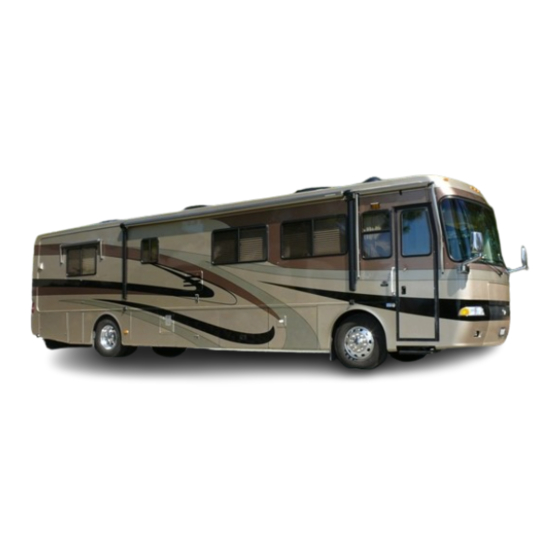
Page 58: Views
Driving & Safety --------------------------------------------------------------------------------------------------------------------------------------------------------------------------------------------------------------------------------------------------------------------------------------------------------------------- VIEWS Front Front 6. License Plate 1. Mirrors (Remote Heat Optional) 7. Fog Lights 2. Headlights 8. Identification Lights 3. Clearance Lights 4. Generator Compartment/ Front Hood 5. Windshield Wipers Rear Rear 7. Engine Compartment 1. Clearance Lights 8. -
Page 59: Roadside & Curbside
Driving & Safety ------------------------------------------------------------------------------------------------------------------------------------------------------------------------------------------------------------------------------------------------------------------------------------------------------------------ Roadside Locations may vary from model to model. Identify each by their specific view. 1. Shore Power Electric Receptacle 7. Side Marker Light 2. Chassis Electrical Panel 8. Roof Air Conditioner 3. LP Tank Fill and Shut-Off Valves 9. -
Page 60: Smoke Detector
Driving & Safety --------------------------------------------------------------------------------------------------------------------------------------------------------------------------------------------------------------------------------------------------------------------------------------------------------------------- SMOKE DETECTOR Statistics show that most fire casualties are not caused by direct flame, but by less visible smoke (products of combustion). The smoke detector responds to both visible and invisible products of combustion. The smoke detector will automatically return from alarm to normal state when the reason for activation, the presence of smoke, is completely removed. -
Page 61: Troubleshooting
Driving & Safety ------------------------------------------------------------------------------------------------------------------------------------------------------------------------------------------------------------------------------------------------------------------------------------------------------------------ Troubleshooting If the alarm does not sound when the test button is pushed, or with a smoke test, try the following: • Inspect for obvious damage. • Check for the recommended battery type. • Check the battery for proper connection, or replace the battery if needed. -
Page 62: Testing
Driving & Safety --------------------------------------------------------------------------------------------------------------------------------------------------------------------------------------------------------------------------------------------------------------------------------------------------------------------- The gas detector operates on 12 Volt DC, with a current draw less than 1/10th of one amp. CAUTION: This detector will not alarm during the 3 minute warm up cycle. Press the TEST switch any time during the warm up cycle or while in nor- Testing mal operation. -
Page 63: Carbon Monoxide Detector
Driving & Safety ------------------------------------------------------------------------------------------------------------------------------------------------------------------------------------------------------------------------------------------------------------------------------------------------------------------ Fault Alarm: Should the microprocessor sense a fault in the gas detector, a fault alarm will sound twice every 15 seconds. The LED will alternately flash Red to Green and the MUTE switch will not respond to any command. The gas detector must be repaired or replaced. -
Page 64: Alarm
Driving & Safety --------------------------------------------------------------------------------------------------------------------------------------------------------------------------------------------------------------------------------------------------------------------------------------------------------------------- power is on and the connections are correct, but the indicator still does not light, the detector should be returned for service. Do not attempt to fix the detector. The indicator light displays a specific color to monitor the condi- tions as follows: •... -
Page 65: Fire Extinguisher
Driving & Safety ------------------------------------------------------------------------------------------------------------------------------------------------------------------------------------------------------------------------------------------------------------------------------------------------------------------ FIRE The fire extinguisher in the motorhome is located near EXTINGUISHER the main entrance door. Please read the operating instruc- Operation tions that are printed on the fire extinguisher. If there is any doubt on how to operate the fire extinguisher, you and your family should practice using it. - Page 66 Driving & Safety --------------------------------------------------------------------------------------------------------------------------------------------------------------------------------------------------------------------------------------------------------------------------------------------------------------------- NOTE W I N D S O R 2 • 6 6...
- Page 67 SECTION 3 CARE & MAINTENANCE EXTERIOR CARE • 69 Corrosion • 69 Washing • 69 Drying • 70 Waxing • 70 Tire Care • 71 Care & Maintenance of Aluminum Wheels • 71 Bright Metal • 72 Maintenance - Exterior • 72 Roof Care &...
-
Page 69: Care & Maintenance
Care & Maintenance -------------------------------------------------------------------------------------------------------------------------------------------------------------------------------------------------------------------------------------------------------------------------------------------------------------------- EXTERIOR CARE The most common cause of corrosion to the motorhome is the accumula- Corrosion tion of road salts, grime and dirt. These elements, combined with moisture, may possibly cause early component failure. Salt air and fog from coastal trips can greatly accelerate the corrosion process. -
Page 70: Drying
• If the surface is not waxed, what is protecting the surface from the environment (road salts, acid rain, road tar, ultraviolet light)? Monaco Coach Corporation recommends the use of wax, twice a year; spring and fall. Many types of protective barriers are available today that may be applied to the clear coat: glazes, waxes, polishes, rubbing compunds or combinations of these products. -
Page 71: Tire Care
Care & Maintenance -------------------------------------------------------------------------------------------------------------------------------------------------------------------------------------------------------------------------------------------------------------------------------------------------------------------- inconspicuous area in case an undesired reaction occurs. Observe the test area from different angles checking for hazing or swirl marks. If an abnormal reaction to the finish results, discontinue product use and consult the prod- uct’s manufacturer. -
Page 72: Bright Metal
Care & Maintenance ---------------------------------------------------------------------------------------------------------------------------------------------------------------------------------------------------------------------------------------------------------------------------------------------------------------------------------- 2. Rinse thoroughly with clean water. 3. Wipe dry to avoid water spots. 4. Use a high quality, non-abrasive polish to remove stubborn road tars, insects or hard to remove deposits. 5. To protect the appearance surface on Accu-Forge wheels, wax the cleaned sur- face with a high quality car wax. - Page 73 Care & Maintenance -------------------------------------------------------------------------------------------------------------------------------------------------------------------------------------------------------------------------------------------------------------------------------------------------------------------- ing vents, skylights, roof mounted antennas, windows, door molding, clearance lights and the beltline molding. Specific sealant products should be used in the areas for which they were designed. These items can be obtained from recreational vehicle parts suppliers.
-
Page 74: Interior Care •74
Care & Maintenance ---------------------------------------------------------------------------------------------------------------------------------------------------------------------------------------------------------------------------------------------------------------------------------------------------------------------------------- Acrylic Sealants (geocel 2300): This product is used where items are sealed under a painted surface such as the metal corners of the slide out room. The material is specially formulated to allow paint adhesion. Spray Foam: This product is used as a sealant where a hole has been made for items such as water lines or wires that are coming through a floor open- ing. - Page 75 Care & Maintenance -------------------------------------------------------------------------------------------------------------------------------------------------------------------------------------------------------------------------------------------------------------------------------------------------------------------- “S” - Clean this fabric with pure solvents (petroleum distillate-based prod- ucts such as Energine, Carbona, Renuzit, or similar products may be used) in a well ventilated room. Cleaning only by a professional furniture cleaning service is recommended.
-
Page 76: Fabric Specifications Chart
Care & Maintenance ---------------------------------------------------------------------------------------------------------------------------------------------------------------------------------------------------------------------------------------------------------------------------------------------------------------------------------- FABRIC SPECIFICATION CHART: CLEANING FABRIC CONTENT APPLICATION CODE Autumn .413 74% Cotton, 17% Rayon, $% Current BGE - 3 Sofa, Living Room Pillow Linen, 4% Acrylic, 1% Poly Living Room Pillow, Free standing Angel Falls - FL Dawn 87% Cotton, 13% Polyester Dinette Chair, Dinette Cushions, Living Room Lambrequin... - Page 77 Care & Maintenance -------------------------------------------------------------------------------------------------------------------------------------------------------------------------------------------------------------------------------------------------------------------------------------------------------------------- CLEANING FABRIC CONTENT APPLICATION CODE Twilight 415 Hollywood Hills 002 50% Polyester, 50% Rayon Sofa, Living Room Lambrequin Living Room Accent, Free Standing Cinematiquei 001 50% Polyester, 50 Rayon Dinette Chair Living Room Lambrequin, Chair, Lamour 013 50% Polyester, 50 % Rayon Living Room Pillow, Dinette Cushion Captiva - FS Cinder...
-
Page 78: Vinyl
Care & Maintenance ---------------------------------------------------------------------------------------------------------------------------------------------------------------------------------------------------------------------------------------------------------------------------------------------------------------------------------- Vinyl Several areas of the motorhome can be covered in vinyl. These areas include the dash, items of furniture and the ceiling. The care and cleaning of these areas are out- lined in the Morbern Vinyl section below. Morbern Vinyl: Vinyl requires periodic cleaning to maintain its neat appearance and to prevent the buildup of dirt and contaminants that may permanently stain... - Page 79 Care & Maintenance -------------------------------------------------------------------------------------------------------------------------------------------------------------------------------------------------------------------------------------------------------------------------------------------------------------------- CAUTION: Any lacquer solvent will cause immediate irrepara- ble damage to the vinyl. Wax should never be used on any vinyl upholstery, as it will cause premature embrittlement and crack- ing. Dilute chlorine bleach before using. Never use full strength bleach.
-
Page 80: Leather
Care & Maintenance ---------------------------------------------------------------------------------------------------------------------------------------------------------------------------------------------------------------------------------------------------------------------------------------------------------------------------------- Lipstick, Grease, Oil, Make-Up or Shoe Polish: Apply a small amount of mineral spirits with a cloth. Rub gently. Be care- ful not to spread the stain by smearing it beyond its original source. Remove shoe polish immediately as it contains a dye which will cause permanent staining. -
Page 81: Floors - Carpet Cleaning
Care & Maintenance -------------------------------------------------------------------------------------------------------------------------------------------------------------------------------------------------------------------------------------------------------------------------------------------------------------------- NOTE: These are recommended or suggested methods of clean- ing. The manufacturer is not responsible for damage incurred while cleaning. Always test the cleaning method in an incon- spicuous area first before applying to the entire area. Floors - Carpet Cleaning Spot Removal Procedures •... -
Page 82: Floor Tile
Care & Maintenance ---------------------------------------------------------------------------------------------------------------------------------------------------------------------------------------------------------------------------------------------------------------------------------------------------------------------------------- (E) Vinegar Solution: One cup white vinegar to one cup water. (F) Ammonia Solution: One tablespoon household ammonia to one cup water. (G) Spot Removal Kit: Available from retail carpet stores or professional cleaners. (H) Call Professional: Additional suggestions, special cleaning chemicals or the ability to patch the area might be available. -
Page 83: Shower - Cleaning
Care & Maintenance -------------------------------------------------------------------------------------------------------------------------------------------------------------------------------------------------------------------------------------------------------------------------------------------------------------------- NOTE: Before using any solution to clean your tile, check the manufacturer's warning label to ensure the safety of the product. If there is any doubt, apply several test patches of the solution in an inconspicuous place to determine the prod- uct’s suitability. -
Page 84: Wall Coverings
Care & Maintenance ---------------------------------------------------------------------------------------------------------------------------------------------------------------------------------------------------------------------------------------------------------------------------------------------------------------------------------- Wall Coverings Time is very important when removing substances from wall coverings that are solvent based or contain color. Do not use abrasive cleaners containing chlorine bleach or solvents. (Fidelity and Jolie brands are recommended.) Always begin with a mild detergent or soap and warm water. -
Page 85: Countertops
Care & Maintenance -------------------------------------------------------------------------------------------------------------------------------------------------------------------------------------------------------------------------------------------------------------------------------------------------------------------- Countertops Care for the Tower Wall Covering: Remove ordinary stains with mild soap and warm water. Sponge it on. Rinse well and dry with a soft cloth. Special cleaning problems: To remove ball point pen, blood, lipstick, etc., use a sponge or soft bristle brush and Formula 409, Fantastik or a similar product. -
Page 86: Windows
Care & Maintenance ---------------------------------------------------------------------------------------------------------------------------------------------------------------------------------------------------------------------------------------------------------------------------------------------------------------------------------- Other Important Tips: Avoid using strong chemicals on the Solid Surface such as paint removers or oven cleaners. If these come in contact with the Solid Surface quickly wash with water. Avoid contact with nail polish or nail polish remover. If contact is made quickly wash with water. -
Page 87: Mini-Blinds
Care & Maintenance -------------------------------------------------------------------------------------------------------------------------------------------------------------------------------------------------------------------------------------------------------------------------------------------------------------------- • In very cold weather leave the cabinet and closet doors partially open. The air flow will warm and ventilate the interior of the storage compartments and the exterior wall surface, reducing or eliminating condensation and prevent the possibility of ice formations. -
Page 88: Storage Long Term
Care & Maintenance ---------------------------------------------------------------------------------------------------------------------------------------------------------------------------------------------------------------------------------------------------------------------------------------------------------------------------------- • The holding tanks should be drained and fresh water system winterized with potable antifreeze or winterize the plumbing system using air pressure. • Retract and secure all awnings. • Turn the battery cut-off switch OFF. •... - Page 89 Care & Maintenance -------------------------------------------------------------------------------------------------------------------------------------------------------------------------------------------------------------------------------------------------------------------------------------------------------------------- • When stored outside, use the available DC volt meters to make a quick reference check of the batteries while the motorhome is in storage. If the motorhome is stored out- side solar panels may offset the parasitic loads. •...
- Page 90 Care & Maintenance ---------------------------------------------------------------------------------------------------------------------------------------------------------------------------------------------------------------------------------------------------------------------------------------------------------------------------------- help control mold and mildew growth. • Proper winterization of the fresh water system will prevent potential damage in extreme cold. • Ultraviolet radiation affects soft goods and rubber products such as: privacy curtains, window shades and tires. These items should be protected.
-
Page 91: Checklist
Care & Maintenance -------------------------------------------------------------------------------------------------------------------------------------------------------------------------------------------------------------------------------------------------------------------------------------------------------------------- friction action of the linings. Engine: • Internal combustion engines need to be “exercised” on a regular basis. This will ensure that an adequate supply of lubricating oil coats the cylinder walls and piston rings. Valve and valve seat surfaces also suffer from non-use. -
Page 92: Storage Removal
Care & Maintenance ---------------------------------------------------------------------------------------------------------------------------------------------------------------------------------------------------------------------------------------------------------------------------------------------------------------------------------- Storage - Removal If the motorhome was properly and carefully prepared for storage, removing it from storage will not be difficult. The following checklist pertains to items or areas which should be checked before operating or moving the motorhome. If the motorhome was not properly winterized, extensive freeze damage or other serious deterioration may have occurred. - Page 93 Care & Maintenance -------------------------------------------------------------------------------------------------------------------------------------------------------------------------------------------------------------------------------------------------------------------------------------------------------------------- • Check that the monitor panel is functioning properly. • Inspect the 120 Volt electrical system which includes the power cord, inverter/converter all outlets and exposed wiring. NOTE: Prepare the generator for operation following the instructions in the Generator Manual. •...
- Page 94 Care & Maintenance ---------------------------------------------------------------------------------------------------------------------------------------------------------------------------------------------------------------------------------------------------------------------------------------------------------------------------------- NOTES 3 • 9 4 W I N D S O R...
- Page 95 SECTION 4 APPLIANCES INTRODUCTION • 97 AIR CONDITIONER - ROOF • 112 REFRIGERATOR • 97 Heat Pump • 113 Operation Specifics • 98 Operation • 113 Tips • 98 Return Air Filters • 114 Refrigerator Controls • 98 FURNACE • 114 Doors •...
-
Page 97: Introduction
Appliances ------------------------------------------------------------------------------------------------------------------------------------------------------------------------------------------------------------------------------------------------------------------------------------------------------------------ INTRODUCTION This section covers operation and care of various appliances found in the motorhome. The motorhome is equipped with a refrigerator, cooktop, microwave, furnace, water heater, roof air conditioner and several optional appliances. Many of these appliances operate on AC or DC current, LP-Gas, or a combination of all three. -
Page 98: Operation Specifics
Appliances --------------------------------------------------------------------------------------------------------------------------------------------------------------------------------------------------------------------------------------------------------------------------------------------------------------------- Operation The refrigerator operates from either LP-Gas or 120 Volts AC electric. Controls Specifics are electronic which require the DC Voltage to be no higher than 15.4 Volts DC or lower than 10.5 Volts DC. The AC voltage limits are 132 Volts AC maximum and 108 Volts AC minimum. -
Page 99: Doors
Appliances ------------------------------------------------------------------------------------------------------------------------------------------------------------------------------------------------------------------------------------------------------------------------------------------------------------------ Doors The refrigerator doors are positive lock style doors that close with a “click” to prevent accidental door opening while traveling. When storing the motorhome, the refrigerator doors have a storage position that locks the doors partially open. This will help reduce odor from mold and bacteria build-up. Use this feature. -
Page 100: Manual Mode Operation
Appliances --------------------------------------------------------------------------------------------------------------------------------------------------------------------------------------------------------------------------------------------------------------------------------------------------------------------- Manual Mode This mode will lock the refrigerator into either LP-Gas or electric AC opera- Operation tion. Press and hold the MODE button until LP or AC is displayed. Release when the desired function is lit. The Alarm will sound and a code will be displayed if the function selected is interrupted or a failure occurs. -
Page 101: Ice Maker Operation (Optional)
Appliances ------------------------------------------------------------------------------------------------------------------------------------------------------------------------------------------------------------------------------------------------------------------------------------------------------------------ Alarm The refrigerator uses an audible alarm that will sound for the following reasons: 1. DC or AC voltage is higher or lower than allowed specifica- tions. 2. Refrigerator is set to auto mode and the 120 Volts AC is dis- continued. -
Page 102: Cooling Unit Fans (Four Door Models)
Appliances --------------------------------------------------------------------------------------------------------------------------------------------------------------------------------------------------------------------------------------------------------------------------------------------------------------------- High Humidity The refrigerator is equipped with a heating element located in the flapper Operation on the left door (four door model), or in the door (two door model). The heating element is activated when the refrigerator is turned on to any mode to help pre- vent moisture build-up in high humidity conditions. -
Page 103: Hot Water Dispenser (Optional)
Appliances ------------------------------------------------------------------------------------------------------------------------------------------------------------------------------------------------------------------------------------------------------------------------------------------------------------------ Care & Cleaning Clean the interior with mild detergent and warm water. Avoid the use of solvent cleaning agents or abrasives on the interior. These cleaners may transmit taste to the ice cubes and food, or damage and discolor the interior. The exterior may be cleaned with mild detergent and warm water. -
Page 104: Microwave Oven
Appliances --------------------------------------------------------------------------------------------------------------------------------------------------------------------------------------------------------------------------------------------------------------------------------------------------------------------- • Draw three or four cups of water and allow unit to reheat. • Repeat the procedure until desired temperature is reached. DO NOT ALLOW THE WATER TO BOIL. Cleaning Hot Water Dispenser Use only mild cleaners to clean the dispenser spout and plastic components. Use of cleaning agents containing acids, alkalies and organic solvents will result in the deterioration of plastic components. - Page 105 Appliances ------------------------------------------------------------------------------------------------------------------------------------------------------------------------------------------------------------------------------------------------------------------------------------------------------------------ WARNING: If a fire flares up when using the cooktop, turn off the ventilation fan. The fan may spread the flame. If the ventilation fan has started automatically from a heated cooktop, it can not be manually turned off. Turn off the microwave AC circuit breaker or unplug the unit to prevent the flame from getting up into the microwave and spreading the fire.
- Page 106 Appliances --------------------------------------------------------------------------------------------------------------------------------------------------------------------------------------------------------------------------------------------------------------------------------------------------------------------- Press the STOP/CLEAR pad to: • Erase, if you make a mistake during programming. • Cancel the kitchen timer. • Stop the oven temporarily during cooking. (Press the START/TOUCH-ON pad to resume.) • Return the time of day to the display. •...
- Page 107 Appliances ------------------------------------------------------------------------------------------------------------------------------------------------------------------------------------------------------------------------------------------------------------------------------------------------------------------ Multiple Sequence Cooking: If sequential cooking times with varied power levels are desired, press the POWER LEVEL pad and select desired power level. Use the number pad to enter cook time for the first interval. Press POWER LEVEL pad again, select desired power level, then enter cook time for the next time period.
-
Page 108: Convection Cooking
Appliances --------------------------------------------------------------------------------------------------------------------------------------------------------------------------------------------------------------------------------------------------------------------------------------------------------------------- Convection Cooking The interior of the microwave produces heat just as it does in a regular oven. The convection cooking mode has special options such as a broil mode, plus the ability to preheat oven by convection and use microwaves to complete cooking or to preheat. -
Page 109: Tips
Appliances ------------------------------------------------------------------------------------------------------------------------------------------------------------------------------------------------------------------------------------------------------------------------------------------------------------------ both functions. Only the cook times can be tailored for individual preference by entering into either the CompuRoast or the CompuBake mode. Press the POWER LEVEL pad once for more cooking time and twice for less cooking time. To use either function, press the desired pad and enter the food type from list next to the mode used. -
Page 110: Care & Cleaning
Appliances --------------------------------------------------------------------------------------------------------------------------------------------------------------------------------------------------------------------------------------------------------------------------------------------------------------------- Care & Cleaning The exterior of the oven is plastic and metal. The interior is metal. Do not use scouring pads, harsh or abrasive cleanser, chemical cleaners or petroleum based thin- ners as these can damage the finish. Use mild soap and water with a damp cloth or paper towel to remove most stains or spills. -
Page 111: Burner Grate
Appliances ------------------------------------------------------------------------------------------------------------------------------------------------------------------------------------------------------------------------------------------------------------------------------------------------------------------ Burner Grate The burner grate is attached to the cooktop cover by two spring clips located on the underside of the cooktop cover. The burner grate can be separated from the cooktop cover for cleaning purposes. Place a towel down onto the countertop next to the cooktop. -
Page 112: Porcelain Enamel
Appliances --------------------------------------------------------------------------------------------------------------------------------------------------------------------------------------------------------------------------------------------------------------------------------------------------------------------- Regular cleaning with a soft cloth and a warm detergent solution is gener- ally enough to keep the cooktop clean. Wash, rinse and dry with a soft cloth. Thoroughly clean the cooktop when it is cool. Use a dry cloth or paper towel while the surface is warm to the touch to clean splatters or spills. -
Page 113: Heat Pump
Appliances ------------------------------------------------------------------------------------------------------------------------------------------------------------------------------------------------------------------------------------------------------------------------------------------------------------------ Heat Pump The heat pump mode offers heat by using the air conditioner as a heat source. The air conditioning principle is reversed, supplying heated air to the ceiling registers instead of refrigerated air. There are ambient temperature limi- tations of the heat pump mode. -
Page 114: Return Air Filters
Appliances --------------------------------------------------------------------------------------------------------------------------------------------------------------------------------------------------------------------------------------------------------------------------------------------------------------------- Return Air Filters The return air filters should be cleaned frequently. They are located on the motorhome ceiling inside the air intake vent covers. Never run the air condi- tioner without the return air filters in place as this may plug the evaporator core with dirt and substantially affect the performance of the air conditioner. -
Page 115: Using The Furnace
Appliances ------------------------------------------------------------------------------------------------------------------------------------------------------------------------------------------------------------------------------------------------------------------------------------------------------------------ CAUTION: Do not store any items or materials in the furnace area. Restricted air flow may hamper furnace operation leading to failure and/or fire hazard. NOTE: The automatic ignition circuit board will attempt to light the burner three times before the ignition board will go into “lock-out.”... -
Page 116: Aqua-Hot (Optional)
Appliances --------------------------------------------------------------------------------------------------------------------------------------------------------------------------------------------------------------------------------------------------------------------------------------------------------------------- AQUA-HOT The Aqua-Hot heat system is specially designed for use in motorhomes. The (Optional) Aqua-Hot is an appliance combining a water heater with a furnace. The Aqua-Hot will provide an almost endless supply of hot water and heat the interior of the motorhome. -
Page 117: Operation
Appliances ------------------------------------------------------------------------------------------------------------------------------------------------------------------------------------------------------------------------------------------------------------------------------------------------------------------ Electric Heat Element The electric element works well if plugged into 50 amp service. If the motorhome is plugged into less than 50 amp service, exercise care so the elec- tric service provided will not be overloaded. Electric operation recovery rate is slower than the diesel burner. -
Page 118: Maintenance
Appliances --------------------------------------------------------------------------------------------------------------------------------------------------------------------------------------------------------------------------------------------------------------------------------------------------------------------- • Select desired temperature setting using the up or down but- tons. NOTE: The blower motor of the heat exchanger in the private bathroom is controlled by the switch in the private bathroom. When the switch is on, the bathroom blower motor will cycle on and off when the hallway heat exchanger blower motor cycles on or off. - Page 119 Appliances ------------------------------------------------------------------------------------------------------------------------------------------------------------------------------------------------------------------------------------------------------------------------------------------------------------------ Draining the Collection Bowl: Water is heavier than fuel and will settle to the bottom of a fuel bowl which will make it appear different in color. In high humidity environments check the collection bowl more than annually. With the engine and the Aqua-Hot off, open the drain to evacuate any contaminants and then close it.
-
Page 120: Water Heater
Appliances --------------------------------------------------------------------------------------------------------------------------------------------------------------------------------------------------------------------------------------------------------------------------------------------------------------------- WATER HEATER Before using the water heater, purge all trapped air from the water system. To purge the air and pressurize the system, fill the fresh water tank by using the on board water pump or hooking up to city water. Check the tank for any obvious water leaks. -
Page 121: Troubleshooting Lp-Gas Operations
Appliances ------------------------------------------------------------------------------------------------------------------------------------------------------------------------------------------------------------------------------------------------------------------------------------------------------------------ • Turn off water heater when not in use to conserve LP-Gas. • The water heater tank capacity is ten gallons. When running the shower, conserve the heated water by shutting the shower water off when not in immediate use. - Page 122 Appliances --------------------------------------------------------------------------------------------------------------------------------------------------------------------------------------------------------------------------------------------------------------------------------------------------------------------- The water heater by design has an internal air pocket to reduce the possibilities of dripping or weeping. The expanding of water, in time, will absorb the air and pocket. The air will have to be replaced utilizing a simple procedure when this occurs.
-
Page 123: Washer/Dryer Prepared
Appliances ------------------------------------------------------------------------------------------------------------------------------------------------------------------------------------------------------------------------------------------------------------------------------------------------------------------ WASHER-DRYER If the motorhome was not ordered with an optional washer-dryer, it will PREPARED have a washer-dryer preparation package installed from the factory. The washer-dryer “prep” package includes the following items: • Color coded water supply lines: red line for hot, blue line for cold. •... -
Page 124: Cleaning The Drain Screen
Appliances --------------------------------------------------------------------------------------------------------------------------------------------------------------------------------------------------------------------------------------------------------------------------------------------------------------------- Operating Before using the washer for the first time, wipe the inside and outside with a Instructions damp cloth to remove any travel dust that has accumulated. Operating a rinse cycle to rinse out the washer is recommended. Front load, horizontal axis wash- ing machines require less detergent. -
Page 125: Cleaning The Washer/Dryer
Appliances ------------------------------------------------------------------------------------------------------------------------------------------------------------------------------------------------------------------------------------------------------------------------------------------------------------------ Cleaning the Occasionally wipe the exterior cabinet of the washer/dryer with a damp Washer/Dryer cloth or sponge. Wipe dry with a soft cloth. Do not use polish on plastic trim. Clean the interior with one cup of chlorine bleach mixed with two cups of granular detergent. - Page 126 Appliances --------------------------------------------------------------------------------------------------------------------------------------------------------------------------------------------------------------------------------------------------------------------------------------------------------------------- NOTES W I N D S O R 4 • 1 2 6...
- Page 127 SECTION 5 EQUIPMENT INTRODUCTION • 129 ENTRY STEP • 129 Operation • 129 Tips • 130 Maintenance & Lubrication • 130 STEP WELL COVER • 131 Front Door Models Only • 131 Adjustments • 131 ENTRY DOOR • 131 Keyless Entry System • 131 Latch Adjustment •...
-
Page 129: Introduction
Equipment ------------------------------------------------------------------------------------------------------------------------------------------------------------------------------------------------------------------------------------------------------------------------------------------------------------------ INTRODUCTION Section Five covers the basic operation and care of various types of equipment found in the motorhome, most of which are provided for entertainment and comfort. More detailed information about specific equipment may be found in that particular manufacturer’s manual. Optional equipment will also be discussed in this section which may not apply to all motorhomes. -
Page 130: Tips
Equipment --------------------------------------------------------------------------------------------------------------------------------------------------------------------------------------------------------------------------------------------------------------------------------------------------------------------- Tips If the step fails to operate: • Make sure the step switch is ON. • Check the main power supply for the step. A 20 amp auto reset 12 Volt DC circuit breaker is located on the rear run plate. •... -
Page 131: Step Well Cover
Equipment ------------------------------------------------------------------------------------------------------------------------------------------------------------------------------------------------------------------------------------------------------------------------------------------------------------------ STEPWELL COVER The motorhome is equipped with a sliding stepwell cover that is extend- Front Door Models ed and retracted by the use of a dual action air cylinder. The air cylinder is Only controlled by an electrically operated air valve. The air solenoid, known as a “MAC”... -
Page 132: Latch Adjustment
Equipment --------------------------------------------------------------------------------------------------------------------------------------------------------------------------------------------------------------------------------------------------------------------------------------------------------------------- Programming a CAUTION: Make sure you have the door keys in your possession Personal Number before changing any codes to use in the event you get locked out of the motorhome. Factory Default Code To Change The Master User Code to PIN 1,3,5 1. -
Page 133: Screen Door - Removing Screen
Equipment ------------------------------------------------------------------------------------------------------------------------------------------------------------------------------------------------------------------------------------------------------------------------------------------------------------------ Make all adjustments in small increments. Tighten the bolt firmly after making adjustments. The bolts should have slight up and down movement for vibration control in travel. • Test the operation of the dead bolt lock to ensure proper functions. •... -
Page 134: Extending Main Room
Equipment --------------------------------------------------------------------------------------------------------------------------------------------------------------------------------------------------------------------------------------------------------------------------------------------------------------------- SLIDE-OUT ROOM To Extend the Slide-Out Room: - Extending Main • Move the driver seat forward before activating the slide-out room. Room • Confirm that there is at least five feet of clearance outside the motorhome for the slide-out room to extend. •... - Page 135 Equipment ------------------------------------------------------------------------------------------------------------------------------------------------------------------------------------------------------------------------------------------------------------------------------------------------------------------ CAUTION: Remove the LOCK’R bar before moving the slide-out room. Damage can result if it is left in position. The manufacturer is not responsible for damage resulting from operating the slide-out room with the LOCK’R left in posi- tion.
-
Page 136: Manual Override - Main Slide-Out
Equipment --------------------------------------------------------------------------------------------------------------------------------------------------------------------------------------------------------------------------------------------------------------------------------------------------------------------- Awning - Main Slide-out The motorhome is equipped with a slide-out awning that will automatically roll out with the slide room when it is extended. When the slide room is extended, the awning can then be rolled out com- pletely as a window awning. -
Page 137: Extending Bedroom
Equipment ------------------------------------------------------------------------------------------------------------------------------------------------------------------------------------------------------------------------------------------------------------------------------------------------------------------ 4. Once the room is in apply pressure to the wrench so that the room is sealed. Return the brake lever to its normal position to lock the room in place. Install the transit bar. 5. Take the motorhome to an authorized dealer for service. NOTE: The slide-out room is heavy and may require several persons to push it into the retracted position. -
Page 138: Retracting Bedroom
Equipment --------------------------------------------------------------------------------------------------------------------------------------------------------------------------------------------------------------------------------------------------------------------------------------------------------------------- 2. Press and hold the slide-out room switch in the OUT position. The slide-out room will move slowly to the OUT position. The drive motor will not stop automatically. To stop the slide-out room before reaching the OUT position, release the switch. To continue room movement, push and hold the switch in. -
Page 139: Manual Override - Bedroom Slideout
Equipment ------------------------------------------------------------------------------------------------------------------------------------------------------------------------------------------------------------------------------------------------------------------------------------------------------------------ Manual Override - The bedroom slide-out system can be retracted in the event of a power Bedroom Slideout loss. If the room does not move when the switch is pressed: • The house battery cut-off switch must be on. •... -
Page 140: Slide Lock
Equipment --------------------------------------------------------------------------------------------------------------------------------------------------------------------------------------------------------------------------------------------------------------------------------------------------------------------- • When the room is out visually inspect the wipe seal. The seal should be clean and free of dirt or other foreign material. Keep the seal dry. Inspect seal for tears and rips. • In the event the slide room leaks, fully retract it. Tape the exterior opening closed with duct tape until repairs to the motorhome can be completed. -
Page 141: Entertainment Center - Home
Equipment ------------------------------------------------------------------------------------------------------------------------------------------------------------------------------------------------------------------------------------------------------------------------------------------------------------------ NOTE: It is not recommended to extend the slide room in snow, sleet, ice or freezing rain. There may be extensive dam- age resulting from the awning freezing. In the event the slide-out room is extended in snow, sleet, ice or freezing rain conditions, it is recommended you clear the awning and ensure free movement prior to retracting the slide room. -
Page 142: Hookups - Tv Cable, Computer & Telephone
Equipment --------------------------------------------------------------------------------------------------------------------------------------------------------------------------------------------------------------------------------------------------------------------------------------------------------------------- WARNING: Do not raise a TV antenna near overhead elec- trical wires as contact may cause serious injury or death. WARNING: The motorhome must not be moved with the antenna in a raised or partially raised position. Worm gear or worm breakage may result. -
Page 143: Video Selector Box
Equipment ------------------------------------------------------------------------------------------------------------------------------------------------------------------------------------------------------------------------------------------------------------------------------------------------------------------ VIDEO SELECTOR The motorhome is equipped with a video selector box located just above the VCR. The selector box receives video and audio signals from three differ- ent sources: the roof mounted antenna, shore cable (Auxiliary)or the VCR. The video selector box directs the signals to either the front or rear TV, and directs the signal from shore cable or the roof mounted antenna to the VCR. -
Page 144: Citizen Band Radio Prewire
Equipment --------------------------------------------------------------------------------------------------------------------------------------------------------------------------------------------------------------------------------------------------------------------------------------------------------------------- from one another. When installing a metal end onto the coax cable, use care so that none of the woven ground strands come in contact with the center conductor. A continuity tester is used to test for a suspected bad coax wire run. - Page 145 Equipment ------------------------------------------------------------------------------------------------------------------------------------------------------------------------------------------------------------------------------------------------------------------------------------------------------------------ SATELLITE The motorhome may have been prewired for a roof mount DSS system. SYSTEM The prewire will consist of a ¾” flexible conduit, which will run from the PREWIRE - DSS front overhead to a spot marked on the roof. A telephone hook-up will also be provided for Pay Per View accessibility.
- Page 146 Equipment --------------------------------------------------------------------------------------------------------------------------------------------------------------------------------------------------------------------------------------------------------------------------------------------------------------------- RADIO - DASH The dash radio will control the multi-functions for the dash audio. The detachable front panel provides anti-theft protection. The tuner holds up to eighteen preset FM stations and twelve AM stations. Other features are an attenuate mode, loudness control, a 12 hour digital clock and autoseek tuning.
- Page 147 Equipment ------------------------------------------------------------------------------------------------------------------------------------------------------------------------------------------------------------------------------------------------------------------------------------------------------------------ 8. SOUND button: Changes display mode. 9. MUTE button: Press to mute sound momentarily. 10. SOURCE/ON button: Press to select program sources. 11. DISC/PRESET UP, & 12. DISC/PRESET DOWN: Press either UP or DOWN button to: • Fast wind the tape. To resume normal playback, press MODE button. •...
- Page 148 Equipment --------------------------------------------------------------------------------------------------------------------------------------------------------------------------------------------------------------------------------------------------------------------------------------------------------------------- Exhaust Fan The exhaust fan is controlled by a wall thermostat and is powered by 12 Volt DC. To operate the fan remove the ceiling grill cover, open the grill dampers and select one of three fan speeds using the round knob on the grill. Set the thermostat to the ON setting for continuous air flow, or to AUTO and the desired air temperature for the ON/OFF air flow.
- Page 149 Equipment ------------------------------------------------------------------------------------------------------------------------------------------------------------------------------------------------------------------------------------------------------------------------------------------------------------------ NOTE: Close the grill dampers before installing the grill cover. Failure to close the damper will result in the cover blowing off while the motorhome is moving. The motorhome is equipped with roof air vents which are FAN - VENT manually operated.
- Page 150 Equipment --------------------------------------------------------------------------------------------------------------------------------------------------------------------------------------------------------------------------------------------------------------------------------------------------------------------- • Release strap slowly ensuring inner arms are secure. Slide the strap to rear of awning roll tube and tie to rear arm. • Loosen locking knobs for both arms and extend arms so the canvas will clear door in the open position.
- Page 151 Equipment ------------------------------------------------------------------------------------------------------------------------------------------------------------------------------------------------------------------------------------------------------------------------------------------------------------------ Awning - Patio To Extend The Patio Awning 1. Hook the loop of the center strap with the pull wand and draw the awning away from the motorhome to the desired extension. Slide the center pull strap to one end of the awning and store it. 2.
- Page 152 Equipment --------------------------------------------------------------------------------------------------------------------------------------------------------------------------------------------------------------------------------------------------------------------------------------------------------------------- Rain Release Setting: After the awning has been extended, choose the rain release position to prevent water build up on the awning. To position the awning in the rain release set- ting lower one arm of the awning and leave the other arm in the normal position.
- Page 153 Equipment ------------------------------------------------------------------------------------------------------------------------------------------------------------------------------------------------------------------------------------------------------------------------------------------------------------------ Saturate the fabric with the solution and leave it on for 15-20 minutes. If necessary, reapply the solution to keep the fabric saturated. Rinse the awning thoroughly. Repeat, if necessary, until most of the stains disappear. • Water Leaks: If leaking occurs after washing it generally results from insufficient rinsing.
- Page 154 Equipment --------------------------------------------------------------------------------------------------------------------------------------------------------------------------------------------------------------------------------------------------------------------------------------------------------------------- • Turn the One touch key to the ON position. • Depress and hold the momentary switch to EXTEND. Motor will automatically stop at full extension. • Allow 14 seconds for awning to reach full extension. • Extension distance or fabric tension is adjusted by toggling between RETRACT and EXTEND.
- Page 155 Equipment ------------------------------------------------------------------------------------------------------------------------------------------------------------------------------------------------------------------------------------------------------------------------------------------------------------------ 1. Two exposed electrical studs are mounted externally at the forward end of the awning at the motor assembly. An alter- nate 12 Volt DC positive and negative supply may be supplied to these connections. If awning fails to move, reverse the polarity of the alternate supply leads.
- Page 156 Equipment --------------------------------------------------------------------------------------------------------------------------------------------------------------------------------------------------------------------------------------------------------------------------------------------------------------------- Sleeper to Sofa • Lift the seat base up until seat and back rest are in a V shape. • Push down on seat base. • The booth dinette easily converts into a bed. DINETTE BED • Lift seat cushions to an angled vertical position. CONVERSTION •...
- Page 157 SECTION 6 WATER SYSTEMS WATER SYSTEMS • 159 General Information • 159 MONITOR PANEL • 159 Measurement & Calibration • 159 WATER TANK - FRESH WATER FILL • 160 MANABLOC PLUMBING MANIFOLD • 160 WATER - CITY HOOK-UP • 161 WATER PUMP •...
-
Page 159: Water Systems
Water Systems ------------------------------------------------------------------------------------------------------------------------------------------------------------------------------------------------------------------------------------------------------------------------------------------------------------------ WATER SYSTEMS This section contains information on the operation and care of the various General Information water system equipment found in the motorhome. The motorhome is equipped with two separate water systems. Optional water equipment will also be dis- cussed, so not all information may be applicable to your motorhome. -
Page 160: Water Tank - Fresh Water Fill
Water Systems --------------------------------------------------------------------------------------------------------------------------------------------------------------------------------------------------------------------------------------------------------------------------------------------------------------------- Calibration: The monitor panel is calibrated at the factory for accuracy and should not require adjustment. If the system is displaying incorrectly calibration may be necessary. To calibrate: • Completely fill the tank to be calibrated. • Locate the three adjustment screws (one for each tank) behind the monitor panel. -
Page 161: Water - City Hook-Up
Water Systems ------------------------------------------------------------------------------------------------------------------------------------------------------------------------------------------------------------------------------------------------------------------------------------------------------------------ WATER - • Connect the hose to city/fresh water hook-up located in service center CITY HOOK-UP on the roadside of motorhome. • The city water valve must remain in closed position. • Turn on the water supply. •... -
Page 162: Water Pump
Damage from neglect will be the responsibility of the owner, not Monaco Coach Corporation. Latching Controller The latching controller circuitry allows multiple switch loca- tions to operate the water pump. Pressing one of the water pump switches provides a momentary ground signal to the latching controller, turning the water pump on or off from any location. -
Page 163: Troubleshooting
Water Systems ------------------------------------------------------------------------------------------------------------------------------------------------------------------------------------------------------------------------------------------------------------------------------------------------------------------ Troubleshooting Vibration induced by road conditions can cause the plumbing or pump hardware to loosen. Check for system components that are loose. Many symptoms can be resolved by tightening the hardware. Check the following items: The water pump will not start/blows the fuse: •... -
Page 164: Water Filter
Water Systems --------------------------------------------------------------------------------------------------------------------------------------------------------------------------------------------------------------------------------------------------------------------------------------------------------------------- The water pump is noisy or rough in operation: • Check for plumbing which may have vibrated loose. • Does the mounting surface multiply noise (flexible)? • Check for mounting feet that are loose or compressed too tight. •... -
Page 165: Water System
Water Systems ------------------------------------------------------------------------------------------------------------------------------------------------------------------------------------------------------------------------------------------------------------------------------------------------------------------ WATER SYSTEM Water system problems and leaks usually fall into two categories: system Troubleshooting problems and problems caused by improper use or lack of attention. These problems usually stem from improper winterizing, poor maintenance, road vibration and campsite water pressure variations. Check all plumbing connec- tions for leaks at least once a year. -
Page 166: Tank Capacities (Approximate)
Water Systems --------------------------------------------------------------------------------------------------------------------------------------------------------------------------------------------------------------------------------------------------------------------------------------------------------------------- • Drain the fresh water tank. Close the drain and pump the solution (if desired) into the fresh water tank using an independently oper- ated pump and a garden hose connected to City Water Hook-Up on the water control panel. It can be poured into the fresh tank using the gravity fill and a funnel. -
Page 167: Waste Water Systems
Water Systems ------------------------------------------------------------------------------------------------------------------------------------------------------------------------------------------------------------------------------------------------------------------------------------------------------------------ WASTE WATER The waste drainage system was designed to provide adequate and safe stor- SYSTEM age and/or discharge of waste materials. All materials used in fabrication and Waste Drain & installation of system is tested by a nationally recognized testing laboratory. Sewage Tanks The entire fabricated waste system is factory tested in accordance with American National Standards Code A119.2. -
Page 168: Toilet
Water Systems --------------------------------------------------------------------------------------------------------------------------------------------------------------------------------------------------------------------------------------------------------------------------------------------------------------------- TOILET The toilet operates from either fresh water tank or city water supply. The water Operating pump must be turned on or the city water connected. The toilet flushes directly into Instructions a sewage holding tank (black water). •... -
Page 169: Drain Traps & Auto Vents
Water Systems ------------------------------------------------------------------------------------------------------------------------------------------------------------------------------------------------------------------------------------------------------------------------------------------------------------------ NOTE: Most chemical mixtures for holding tank odor con- trol are poisonous. Follow the product manufacturer’s directions and warnings when using any holding tank additive. Sinks, shower and clothes washer drains incorporate a water trap or Drain Traps & “P-trap”... - Page 170 Water Systems --------------------------------------------------------------------------------------------------------------------------------------------------------------------------------------------------------------------------------------------------------------------------------------------------------------------- The grey water holding tank valve (small valve) remains open when con- nected to the sewer hook-up. The black water holding tank valve (large valve) remains closed at all times except when dumping the sewage tank. When preparing to dump the black water holding tank, first close the grey water tank valve.
-
Page 171: What To Put Into The Holding Tanks - Black Water Tank
Water Systems ------------------------------------------------------------------------------------------------------------------------------------------------------------------------------------------------------------------------------------------------------------------------------------------------------------------ WARNING: When using the black tank flush do not leave the motorhome unattended or flooding may occur. The sewage tank flush system should be used each time the black water holding tank is dumped. Failure to routinely use the sewage flush system will result in a clogged spray nozzle. -
Page 172: Bay Heater Operation
Water Systems --------------------------------------------------------------------------------------------------------------------------------------------------------------------------------------------------------------------------------------------------------------------------------------------------------------------- Bay Heater The heater is controlled using two switches, one on the heater itself and a Operation remote “SYSTEMS HEAT’ switch located in an inside overhead compartment next to entrance door. Both switches must be in ON position for the heater to operate. -
Page 173: Winterizing
Water Systems ------------------------------------------------------------------------------------------------------------------------------------------------------------------------------------------------------------------------------------------------------------------------------------------------------------------ How you decide to store your motorhome and protect the water lines is up to you. You may elect to have the water lines blown out with air to remove standing water or fill the lines using an approved FDA RV antifreeze. When using either method, all the interior and exterior faucets will need to be opened and closed, one at a time, to verify that all water has been purged. -
Page 174: Fresh Water System Using Nontoxic Antifreeze
Water Systems --------------------------------------------------------------------------------------------------------------------------------------------------------------------------------------------------------------------------------------------------------------------------------------------------------------------- run into the black tank to protect the valve. Pour the last pint of antifreeze into the toilet after you have released the flush button. Micropher toilets may be stopped in the middle of the flush cycle. Locate the on/off switch below the tank lid. Initiate the flush cycle then turn the switch off in the middle of the flush cycle. - Page 175 Water Systems ------------------------------------------------------------------------------------------------------------------------------------------------------------------------------------------------------------------------------------------------------------------------------------------------------------------ WARNING: You should use only non-toxic RV antifreeze that is specifically made for potable water systems. Automotive antifreeze, if ingested, can cause blindness, deafness or death. WARNING: It is recommended that this procedure be done by a qualified RV service technician familiar with motorhomes, such as your authorized selling dealer.
- Page 176 Water Systems --------------------------------------------------------------------------------------------------------------------------------------------------------------------------------------------------------------------------------------------------------------------------------------------------------------------- N O T E S W I N D S O R 6 • 1 7 6...
- Page 177 SECTION 7 LP-GAS SYSTEMS LP-GAS SYSTEM • 179 LP-GAS DETECTOR • 180 Operation • 180 Testing • 180 Care of the Detector • 181 MONITOR PANEL MEASUREMENT & CALIBRATION • 182 CHECKLIST - LP-GAS EMERGENCY PROCEDURES • 182 LP-GAS TANK • 183 Operation •...
-
Page 179: Lp-Gas System
LP-Gas System ------------------------------------------------------------------------------------------------------------------------------------------------------------------------------------------------------------------------------------------------------------------------------------------------------------------ LP-GAS SYSTEM This section contains information and knowledge for the operation and care of the various Liquefied Petroleum (LP-Gas) system equipment found in the motorhome. The motorhome is equipped with several appliances and vari- ous equipment which are capable to operate on LP-Gas. Some items discussed may not be applicable to your motorhome. -
Page 180: Lp-Gas Detector
LP-Gas System --------------------------------------------------------------------------------------------------------------------------------------------------------------------------------------------------------------------------------------------------------------------------------------------------------------------- LP-GAS DETECTOR Provided for safety is a gas detector. This gas detector will detect both LP- Gas and Methane Gas. Liquefied Petroleum (LP) Gas is heavier than air, Methane Gas is lighter than air. LP-Gas will settle to the lowest point, generally the floor of the motorhome. -
Page 181: Care Of The Detector
LP-Gas System ------------------------------------------------------------------------------------------------------------------------------------------------------------------------------------------------------------------------------------------------------------------------------------------------------------------ The Red LED will flash and the alarm will sound whenever a dangerous level of propane or methane gas is detected. The detector will continue to alarm until the gas clears or the Mute switch is pressed. Procedures To Take During An Alarm: 1. -
Page 182: Monitor Panel Measurement & Calibration
LP-Gas System --------------------------------------------------------------------------------------------------------------------------------------------------------------------------------------------------------------------------------------------------------------------------------------------------------------------- MONITOR PANEL Tank Measurement - To measure level of a tank simply push button on dis- MEASUREMENT play panel corresponding to tank you wish to measure. Lights on panel will turn & CALIBRATION on in sequence indicating level of tank. Calibration - The monitoring panel comes factory calibrated for accuracy and should not need to be adjusted. -
Page 183: Lp-Gas Tank
LP-Gas System ------------------------------------------------------------------------------------------------------------------------------------------------------------------------------------------------------------------------------------------------------------------------------------------------------------------ LP-GAS TANK Woodall’s Campground and Trailer Guide and other simi- lar publications list refueling stations. Many travel parks sell LP-Gas. Shut off the pilot lights, appliances and igniters before filling the LP-Gas tank to prevent a fire or explosion. Have a trained service person fill the LP-Gas tank. -
Page 184: Lp-Gas Regulator
LP-Gas System --------------------------------------------------------------------------------------------------------------------------------------------------------------------------------------------------------------------------------------------------------------------------------------------------------------------- the motorhome is in between trips. • Hand tighten the manual valve. Do not use a wrench or pliers to close the valve. • The manual valve is designed to be closed by hand, over tightening may permanently damage the valve seat. The regulator is the heart of an LP-Gas system. -
Page 185: Lp-Gas Consumption
LP-Gas System ------------------------------------------------------------------------------------------------------------------------------------------------------------------------------------------------------------------------------------------------------------------------------------------------------------------ WARNING: Do not attempt to adjust the regulator, it is preset at the factory. If adjustments need to be made it requires spe- cial equipment. Failure to follow these instructions may result in a fire or explosion and cause severe personal injury or death. -
Page 186: Lp-Gas Fundamentals
LP-Gas System --------------------------------------------------------------------------------------------------------------------------------------------------------------------------------------------------------------------------------------------------------------------------------------------------------------------- LP-GAS # Capacity Gallon Capacity BTU Capacity FUNDAMENTALS 1.18 107,903 2.36 215,807 2.59 237,387 4.72 431,613 7.08 647,420 9.43 863,226 CONVERSIONS Gallons to Liters (1 Gallon = 3.785 Liters) Fahrenheit to Celsius (F° = 9/5 C° + 32°) 11”... - Page 187 SECTION 8 ELECTRICAL SYSTEM - HOUSE INTRODUCTION • 189 DISTRIBUTION PANEL - HOUSE 110 • 206 Shore Power • 189 AC Panel • 206 Power Cord Reel (Optional) • 189 Circuit Breaker • 208 Generator • 190 ENERGY MANAGEMENT SYSTEM Inverter/Converter •...
-
Page 189: Power Cord Reel (Optional)
Electrical Systems - House ------------------------------------------------------------------------------------------------------------------------------------------------------------------------------------------------------------------------------------------------------------------------------------------------------------------ INTRODUCTION The motorhome 120/240 Volt AC system can be operated from three different power sources. Shore power is the most efficient and should be used whenever possible. The on board generator has a limited amount of 120 Volts AC output power. -
Page 190: Generator
Electrical Systems - House --------------------------------------------------------------------------------------------------------------------------------------------------------------------------------------------------------------------------------------------------------------------------------------------------------------------- Maintenance: When only a short section of the shore power cable is frequently used the cable may coil sharper than normal, causing kinking of the cable. To relieve this condition, routinely extend the cable full distance. Straighten the power cable on the ground. -
Page 191: Battery Disconnect - House
Electrical Systems - House ------------------------------------------------------------------------------------------------------------------------------------------------------------------------------------------------------------------------------------------------------------------------------------------------------------------ BATTERY The main house battery disconnect switch turns the battery power supply DISCONNECT - on or off. The domestic battery disconnect switch shuts off the 12 Volt DC HOUSE power to the following items: the inverter, the domestic fuse panel in the bedroom, the domestic fuse panel in the front run box and the domestic power supply in the rear run box(s). -
Page 192: Battery Cut-Off Switch
Electrical Systems - House --------------------------------------------------------------------------------------------------------------------------------------------------------------------------------------------------------------------------------------------------------------------------------------------------------------------- BATTERY CUT-OFF SWITCH The battery cut-off switch is located inside and next to the entry door. This switch controls the 12 Volt DC power to the domestic fuse panels. When the switch is ON power is supplied to all interior DC lighting and DC operated appliances. -
Page 193: Generator - 120 Ac
Electrical Systems - House ------------------------------------------------------------------------------------------------------------------------------------------------------------------------------------------------------------------------------------------------------------------------------------------------------------------ Transfer Switch The transfer switch automatically transfers power from the shore power cord or generator through the transfer switch to the 110 Volt AC breaker panel. When the generator is used as the power source the transfer switch has a time delay built into it. -
Page 194: Starting The Generator
Electrical Systems - House --------------------------------------------------------------------------------------------------------------------------------------------------------------------------------------------------------------------------------------------------------------------------------------------------------------------- Starting the Push and hold control switch in START position until the generator starts. Generator Release switch. On diesel models the control switch may flash up to 15 seconds, indicating engine preheat. NOTE: Diesel models may require priming. Hold control switch in the OFF position for one minute. -
Page 195: Powering The Equipment
Electrical Systems - House ------------------------------------------------------------------------------------------------------------------------------------------------------------------------------------------------------------------------------------------------------------------------------------------------------------------ Powering The The AC output of the generator powers the motorhome air conditioners, Equipment the AC inverter/converter charger, all appliances and items plugged into the electrical outlets of the motorhome. The number of electrical appliances that can be operated at any given time depends upon how much power is avail- able from the generator. -
Page 196: Inverter/Converter
Electrical Systems - House --------------------------------------------------------------------------------------------------------------------------------------------------------------------------------------------------------------------------------------------------------------------------------------------------------------------- NOTE: An appliance or load may have a short if it causes a circuit breaker to trip after reconnection. DO NOT continue to reset breaker. Have the problem corrected before resuming operation. Generator Exercise If use of the generator is infrequent, “exercise” the generator once a month by operating it at approximately half the maximum rated output for two hours. -
Page 197: Battery Charging With The Inverter
Electrical Systems - House ------------------------------------------------------------------------------------------------------------------------------------------------------------------------------------------------------------------------------------------------------------------------------------------------------------------ Stand-by Operation The inverter can be set-up for stand-by power operation. If AC input is discontinued to the motorhome, the inverter will automatically provide AC power. When AC power is resumed, the inverter will automatically return to “stand-by”... -
Page 198: Battery Temperature Sensor
Electrical Systems - House --------------------------------------------------------------------------------------------------------------------------------------------------------------------------------------------------------------------------------------------------------------------------------------------------------------------- Battery Temperature The inverter uses a battery temperature sensor to adjust charge voltage. Sensor When the battery temperature rises the BTS will send this information, registering as counts, to the inverter to decrease charge voltage. Voltage compensation with temperature variation is necessary to keep charge volt- age at optimum figures. -
Page 199: Meter Menu
Electrical Systems - House ------------------------------------------------------------------------------------------------------------------------------------------------------------------------------------------------------------------------------------------------------------------------------------------------------------------ Meter Menu This is an alternate field of main system status. To access the various meters available, depress the UP arrow button and hold for five seconds. The RC7 GS remote will beep. Release the button. The Avg Shunt Amps will be displayed. -
Page 200: Programming The Rc 7 Gs
Electrical Systems - House --------------------------------------------------------------------------------------------------------------------------------------------------------------------------------------------------------------------------------------------------------------------------------------------------------------------- Programming To enter programming mode: the RC 7 GS • Press and hold the Set-Up buttons (up and down arrows) for five seconds. The RC7 GS remote will beep. • Release the buttons. The programming mode has been entered when the Search Sense is displayed. - Page 201 Electrical Systems - House ------------------------------------------------------------------------------------------------------------------------------------------------------------------------------------------------------------------------------------------------------------------------------------------------------------------ Battery Capacity: The battery bank capacity is adjustable in Ahrs (amp hours). These set- tings change charging curves and the length of time of the charging cycles. The range is from 125 Ahrs to 1,000 Ahrs. Select the closest Amp Hour rat- ing for the house battery bank capacity.
-
Page 202: Automatic Generator Start
Electrical Systems - House --------------------------------------------------------------------------------------------------------------------------------------------------------------------------------------------------------------------------------------------------------------------------------------------------------------------- External Shunt: The inverter monitors both AC and DC current values, whether charging or discharging (figures are approximate), by using internal or external shunts. A shunt monitors partial current consumption, allowing the majority of current to pass on heavier conductors. - Page 203 Electrical Systems - House ------------------------------------------------------------------------------------------------------------------------------------------------------------------------------------------------------------------------------------------------------------------------------------------------------------------ voltage obtains a percentage of state of charge (SOC). When selecting the field reference points make sure that the start and stop points are spread apart. It is possible to set parameters too close, causing short cycling of the generator.
-
Page 204: Equalize Charging
Select Generator: The inverter has the capability to operate more than one generator manufacturer type. The selections are: • Onan Quiet Diesel (Type used in Monaco Coach). • Power Tech, two and three wire. • Other 30-80 (reserved for future). - Page 205 Electrical Systems - House ------------------------------------------------------------------------------------------------------------------------------------------------------------------------------------------------------------------------------------------------------------------------------------------------------------------ charge initiate the equalize cycle after the batteries have entered float charge. Only liquid lead acid or absorb glass matte (AGM) type batteries should be equalize charged. Other battery types can be damaged if equalize charged. Monitor the electrolyte solution close- ly when equalizing a liquid lead acid battery.
-
Page 206: Re-Booting The Inverter
Electrical Systems - House --------------------------------------------------------------------------------------------------------------------------------------------------------------------------------------------------------------------------------------------------------------------------------------------------------------------- • Allow the batteries to cool for approximately three hours. Check the electrolyte solution with a hydrometer. Avoid overcharging the battery resulting in damage to the healthy cells. • Add distilled water if necessary. Install battery caps. Use large quantities of fresh water to rinse the entire battery compartment and surrounding area. - Page 207 Electrical Systems - House ------------------------------------------------------------------------------------------------------------------------------------------------------------------------------------------------------------------------------------------------------------------------------------------------------------------ On/I On/I On/I On/I On/I On/I On/I On/I On/I OFF/O OFF/O OFF/O OFF/O OFF/O OFF/O OFF/O OFF/O OFF/O MAIN 4L54 SMART ENERGY MANAGEMENT SYSTEM MODEL 700 Intelllitec 50 AMP SERVICE MADE IN THE U.S.A. LISTED ENCLOSED ENERGY MANAGEMENT EQUIPMENT WARNING: This panel contains high voltage which can cause serious injury or death.
-
Page 208: Circuit Breaker
Electrical Systems - House --------------------------------------------------------------------------------------------------------------------------------------------------------------------------------------------------------------------------------------------------------------------------------------------------------------------- Circuit Breaker Breaker current ratings are current set points in which the breaker is designed to operate. The internal configuration of the circuit breaker is designed to trip when excess current is drawn through the breaker. The trip action of the circuit breaker can occur within milliseconds due to the speed at which electric- ity can travel. - Page 209 Electrical Systems - House ------------------------------------------------------------------------------------------------------------------------------------------------------------------------------------------------------------------------------------------------------------------------------------------------------------------ Circuit Breakers: The distribution panel offers slots for eight single or dual, standard 120 Volt circuit breakers. Two of these breakers, located in the two center stab positions, must be a 50 Amp unit that act as a main input pro- tection for each of the lines supplying the remainder of the branch breakers (up to 12).
- Page 210 Electrical Systems - House --------------------------------------------------------------------------------------------------------------------------------------------------------------------------------------------------------------------------------------------------------------------------------------------------------------------- Through this process the system has “learned” the amount of current that each particular load draws. This feature compensates for the differences in current draw over a range of line voltage and ambient temperature, by re-learning the load each time it is turned off or “shed.”...
-
Page 211: Distribution Panel - House 12 Volt
Electrical Systems - House ------------------------------------------------------------------------------------------------------------------------------------------------------------------------------------------------------------------------------------------------------------------------------------------------------------------ The 20 Amp service mode is not automatically detected and the oper- ator must manually select the 20 Amp mode when 20 Amp service is available. The service select button allows the current threshold to be set to either 30 Amps or 20 Amps to match the incoming service. -
Page 212: Tools Of The Trade
Electrical Systems - House --------------------------------------------------------------------------------------------------------------------------------------------------------------------------------------------------------------------------------------------------------------------------------------------------------------------- The large variety of applications this voltage is used for makes it common AMPERAGE COLOR BLACK for most of the recreational vehicle and automotive industries. The danger from GRAY shocks with this voltage is minimized, but can still occur. A good example of VIOLET this is when a magnetic field is generated, then collapses when the power sup- PINK... -
Page 213: Battery - How It Works
Electrical Systems - House ------------------------------------------------------------------------------------------------------------------------------------------------------------------------------------------------------------------------------------------------------------------------------------------------------------------ WARNING: If a fuse blows, replace the fuse with same amperage rating and type. Installing higher amperage fuses can damage the wiring or the item the fuse is protecting, or may cause a fire. If the fuse repeatedly blows after replacing it, do not continue to replace it. -
Page 214: Deep Cycle Battery
Electrical Systems - House --------------------------------------------------------------------------------------------------------------------------------------------------------------------------------------------------------------------------------------------------------------------------------------------------------------------- Deep Cycle Deep cycle batteries are best suited for use with 12 volt operated lights, Battery appliances and inverters. Deep cycle batteries are designed to have a majority of their capacity used before being recharged. These are available in many sizes and types, the most common is a non-sealed, liquid electrolyte battery. -
Page 215: Battery Tray
Electrical Systems - House ------------------------------------------------------------------------------------------------------------------------------------------------------------------------------------------------------------------------------------------------------------------------------------------------------------------ Battery Tray The engine (chassis) and domestic (house) batteries are located in a curbside compartment. The slide-out battery trays are secured in place by a locking mechanism at the front of the trays. To slide the tray out, lift up on the handle and pull until the tray stops. -
Page 216: Seven Reasons Why Batteries Fail
Electrical Systems - House --------------------------------------------------------------------------------------------------------------------------------------------------------------------------------------------------------------------------------------------------------------------------------------------------------------------- chart. Readings between cells should not vary more than 50 points. If one cell in a particular battery bank being tested is at a 50% state of charge while the others are indicating a full charge, charge only that battery to see if the low cell will come up. -
Page 217: Battery Voltage & Current
Electrical Systems - House ------------------------------------------------------------------------------------------------------------------------------------------------------------------------------------------------------------------------------------------------------------------------------------------------------------------ 3. Sulfation: When a battery remains discharged for too long the accumulated lead sul- fate in the plate material solidifies and cannot reenter the electrolyte. When a battery is left in a discharged state the lead sulphate will crystallize. Charging the battery does not move the crystallized lead sulphate off the battery plate. - Page 218 Electrical Systems - House --------------------------------------------------------------------------------------------------------------------------------------------------------------------------------------------------------------------------------------------------------------------------------------------------------------------- Another way of looking at this is to use the analogy of a water pump (a battery is like an electric pump). The pressure in PSI (pounds per square inch) that a pump delivers is like a battery’s voltage. The volume of water in GPM (gallons per minute) is like the electrical current.
-
Page 219: Battery Charge Time & Consumption Rate
Electrical Systems - House ------------------------------------------------------------------------------------------------------------------------------------------------------------------------------------------------------------------------------------------------------------------------------------------------------------------ Battery Charge Time Calculating Run Times: Calculating run time figures when operating 120 & Consumption Rate Volt AC electrical items with an inverter can be exponential. This is due to bat- tery characteristics. Flow characteristics of electrons vary with different battery types and chemical compositions. -
Page 220: Battery Specifications
Electrical Systems - House --------------------------------------------------------------------------------------------------------------------------------------------------------------------------------------------------------------------------------------------------------------------------------------------------------------------- 50% state of charge would net viewing time for the television at approximately 13 hours in ideal conditions. The run time figure will vary greatly with the actual state of charge of the battery bank when the discharge process begins. Ambient temperature, com- bined with other working loads such as lights and parasitic loads applied to bat- teries, affect run times. -
Page 221: Solar Panel (Optional)
The Charge Controller: The Charge Controller was built specifically to meet the needs of Monaco motorhomes. The faceplate has a digital readout that will display one of three readings by means of a slider switch: House Battery Voltage, Amps Charge or Engine Battery Voltage. -
Page 222: Charge Controller Features
Electrical Systems - House --------------------------------------------------------------------------------------------------------------------------------------------------------------------------------------------------------------------------------------------------------------------------------------------------------------------- Charge Controller The RV-30 Charge Controller has many unique features which are listed Features and described below: 1. Battery Charging - The above mentioned parasitic loads affect both the House and Engine batteries. The controller automatically charges both the House and Engine batteries at the same time to deal with this issue. -
Page 223: Bulb Usage - Interior
Electrical Systems - House ------------------------------------------------------------------------------------------------------------------------------------------------------------------------------------------------------------------------------------------------------------------------------------------------------------------ 2. On a bright sunny day the charging amps should be 3.5 to 5 amp for each panel. 3. High winds blow dust and debris around causing dirt build up. Frequently inspect the panels and clean as necessary. CAUTION: Avoid damage to the solar panel controller. - Page 224 Electrical Systems - House --------------------------------------------------------------------------------------------------------------------------------------------------------------------------------------------------------------------------------------------------------------------------------------------------------------------- NOTES W I N D S O R 8 • 2 2 4...
- Page 225 SECTION 9 ELECTRICAL SYSTEM - CHASSIS INTRODUCTION • 227 BATTERY DISCONNECT - CHASSIS • 227 BATTERY CHASSIS • 228 Battery Specifications - Chassis • 229 DASH • 230 Indicator Lamps • 230 Gauges • 232 Switches - Dash • 234 Air Conditioner &...
-
Page 227: Introduction
Electrical Systems - Chassis ------------------------------------------------------------------------------------------------------------------------------------------------------------------------------------------------------------------------------------------------------------------------------------------------------------------ INTRODUCTION A majority of the lighting and appliances are designed to operate from 12 Volt DC (direct current) power. This is why the batteries play such an important role in the function of the motorhome. There are exceptions with appliances such as the microwave or television;... -
Page 228: Battery Chassis
Electrical Systems - Chassis --------------------------------------------------------------------------------------------------------------------------------------------------------------------------------------------------------------------------------------------------------------------------------------------------------------------- nect switch on. This will help prevent the possibility of dead batteries. If an AC source is not available, and the motorhome is not going to be used or is stored more than 48 hours, it is recommended to turn the battery disconnect switch off. -
Page 229: Battery Specifications - Chassis
Electrical Systems - Chassis ------------------------------------------------------------------------------------------------------------------------------------------------------------------------------------------------------------------------------------------------------------------------------------------------------------------ Battery Specifications - Chassis Chassis (25A) (20hr) minutes 12 Volt Chassis 8D-MHD (1) 1400 6 Volt Domestic U2200 (4 each) Battery connections are made in a Series/Parallel connection. Domestic batteries not rated in Cold Cranking Amps (CCA). STATE OF VS. -
Page 230: Dash
Electrical Systems - Chassis --------------------------------------------------------------------------------------------------------------------------------------------------------------------------------------------------------------------------------------------------------------------------------------------------------------------- DASH Indicator Lamps CHECK STOP CHECK COOL- WARNING TRANS WAIT WATER PARK STEP CHARGE BRAKE FUEL START FUEL 1. Check Engine: This is a negative tripped light used only with the ISC Engine. Indicates water has been detected in fuel. 2. - Page 231 Electrical Systems - Chassis ------------------------------------------------------------------------------------------------------------------------------------------------------------------------------------------------------------------------------------------------------------------------------------------------------------------ 7. Check Trans: Alerts of problems related to the Allison Transmission. The light should momentarily illuminate when the ignition is switched ON. When starting the lamp will extinguish indicating the circuits are working properly. If the lamp fails to illuminate or remains on, the transmission needs to be checked immediately.
-
Page 232: Gauges
Electrical Systems - Chassis --------------------------------------------------------------------------------------------------------------------------------------------------------------------------------------------------------------------------------------------------------------------------------------------------------------------- Gauges 1. Air Pressure Gauge: This gauge indicates air system pressures. The normal air system operating pressures are 90 to 120 psi. These air pressures are preset at the factory. If a problem occurs with air system not maintaining normal operating pressure it is an indication of a malfunction in the air system. - Page 233 Electrical Systems - Chassis ------------------------------------------------------------------------------------------------------------------------------------------------------------------------------------------------------------------------------------------------------------------------------------------------------------------ 3. Turbo Boost: Indicates boost pressure produced by engine turbocharger. 4. Tachometer: Displays engine speed in revolutions per minute (RPM). Tachometer reads output pulse of alternator. If tachometer quits, or indicates irratically, have alternator checked immediately. 5.
-
Page 234: Switches - Dash
Electrical Systems - Chassis --------------------------------------------------------------------------------------------------------------------------------------------------------------------------------------------------------------------------------------------------------------------------------------------------------------------- 10. Trans Temp: Shows temperature of transmission fluid. Normal transmission operating temperature is 160-250° F. The maximum transmission to cooler oil temperature is 300° F. Do not let the transmission temperature exceed 275° F. If excessive temperature is indicated stop motorhome and shift to neutral. -
Page 235: Air Conditioner & Heater Controls
Electrical Systems - Chassis ------------------------------------------------------------------------------------------------------------------------------------------------------------------------------------------------------------------------------------------------------------------------------------------------------------------ 9. Light Switch: Pull to first setting or parking lights. Pull all the way out for headlights. Turn right or left to adjust the brightness of the dash lights when lights are turned on. Turn all the way left for inside cockpit lights. 10. - Page 236 Electrical Systems - Chassis --------------------------------------------------------------------------------------------------------------------------------------------------------------------------------------------------------------------------------------------------------------------------------------------------------------------- Evaporator - A tube core and fins are used in the evaporator similar to the condenser. Air is blown through the fins to allow the evaporator to cool and reduce the pressure. Blower and Motor - Just as the condenser has a fan, the evaporator has a fan called the blower.
- Page 237 Electrical Systems - Chassis ------------------------------------------------------------------------------------------------------------------------------------------------------------------------------------------------------------------------------------------------------------------------------------------------------------------ PSIG-On fully charged system the expected pressure that should be seen on the HIGH-SIDE gauge will be around 200 PSGI. NOTE: All systems are charged at the factory with 4.0 lbs of R134A. R-134a Refrigerant: R134a is classified non-explosive, non-flammable and non-corrosive.
- Page 238 --------------------------------------------------------------------------------------------------------------------------------------------------------------------------------------------------------------------------------------------------------------------------------------------------------------------- Diagnosis of Electric Water Valve: Theory of Operation: Monaco Coach models with a center dial temperature control use a potentiometer at the control head for input of desired tempera- ture. The water valve which controls the water flow to the heater core is opened and closed by a stepper motor mounted on the water valve.
- Page 239 Electrical Systems - Chassis ------------------------------------------------------------------------------------------------------------------------------------------------------------------------------------------------------------------------------------------------------------------------------------------------------------------ Dash AC and Heater Control: The system is designed to only provide heating, cooling and defrost capabilities for the pilot/co-pilot area. The system is not capable of heating or cooling the entire motorhome. Blower Speed Control Temperature Control Mode Control Switch Blower Operation:...
- Page 240 Electrical Systems - Chassis --------------------------------------------------------------------------------------------------------------------------------------------------------------------------------------------------------------------------------------------------------------------------------------------------------------------- OFF - The blower motor does not operate. The fresh air inlet door will close minimizing outside air infiltration into the the motorhome. BI-LEVEL - Fresh air is drawn in and discharged through the dash, floor and defrost louvers.
- Page 241 Electrical Systems - Chassis ------------------------------------------------------------------------------------------------------------------------------------------------------------------------------------------------------------------------------------------------------------------------------------------------------------------ TroubleShooting: The dash A/C/Heat system uses a combination of compressed air (developed by the chassis system), vacuum air (developed by the vacuum generator) and electric relays and vacuum switches. Therefore, any repair can be classified in one of five categories. •...
-
Page 242: Diagnostic Plug Location
Electrical Systems - Chassis --------------------------------------------------------------------------------------------------------------------------------------------------------------------------------------------------------------------------------------------------------------------------------------------------------------------- Reduced cooling: 1. Coolant valve not operating correctly. 2. Air passages obstructed. 3. Loose or worn drive belt. 4. Check blower and select switch. 5. Thermostat control valve faulty. 6. Expansion valve faulty. 7. Compressor faulty. 8. -
Page 243: Shifter Panel
Electrical Systems - Chassis ------------------------------------------------------------------------------------------------------------------------------------------------------------------------------------------------------------------------------------------------------------------------------------------------------------------ SHIFTER PANEL Transmission Key Pad: Transmission Shifter The function of each position of the keypad push-button shifter is as follows: • Select the REVERSE gear by pressing R. • Select NEUTRAL by pressing N. The area around the N button is a raised ridge so the driver can orient his hand to the push buttons by touch, without looking at the display. -
Page 244: Switches
Electrical Systems - Chassis --------------------------------------------------------------------------------------------------------------------------------------------------------------------------------------------------------------------------------------------------------------------------------------------------------------------- Switches 1. Drvr Shade: Operates the power sun visor located on driver’s side. 2. Pass Shade: DRVR PASS BLOCK Operates the power sun visor located on SHADE SHADE HEAT passenger side. 3. Block Heat: The length of time that the block heater must be on to be effective depends on the length of time that the engine has been shut down and what the ambient air temperature... -
Page 245: Parking Brake
Electrical Systems - Chassis ------------------------------------------------------------------------------------------------------------------------------------------------------------------------------------------------------------------------------------------------------------------------------------------------------------------ just push the same switch in the opposite direction. When the pedal comes to the end of the traveling distance you will hear a different sound in the noise of the motor. Stop by releasing the switch. Do not continue moving the pedals. Damage to the motor and or fuses may result if operation of the switch contin- ues after reaching the fullest extend or retract position. -
Page 246: Steering Column & Smart Wheel
Electrical Systems - Chassis --------------------------------------------------------------------------------------------------------------------------------------------------------------------------------------------------------------------------------------------------------------------------------------------------------------------- HWH Control (Air Systems): HWH COMPUTERIZED LEVELING The touch panel, computer controlled, four-point air level- ing system is an option available for the motorhome. The key- EXCESS LEVEL SLOPE pad on the system controls the computerized air- leveling operations. -
Page 247: Wiper Functions
Electrical Systems - Chassis ------------------------------------------------------------------------------------------------------------------------------------------------------------------------------------------------------------------------------------------------------------------------------------------------------------------ • Cruise SET - The operation of this switch actuates the Cruise Set function of the engine controller. • Cruise RES - The operation of this switch actuates the Cruise Resume function of the engine controller. •... -
Page 248: Steering Column
Electrical Systems - Chassis --------------------------------------------------------------------------------------------------------------------------------------------------------------------------------------------------------------------------------------------------------------------------------------------------------------------- STEERING Tilt and telescope steering wheel control lever is located COLUMN on the steering column. Tilt & Telescope • To tilt the steering wheel pull the lever up. Tilt the steering wheel where you want it. Release the lever and it will lock the steering wheel in the new posi- tion. - Page 249 Electrical Systems - Chassis ------------------------------------------------------------------------------------------------------------------------------------------------------------------------------------------------------------------------------------------------------------------------------------------------------------------ Circuit Breakers And Fuses House: 1. Bay Door Locks - 10 amp Fuse 2. LP/CO Detector - 3 amp Fuse 3. Power Seat (Driver) -15 amp Circuit Breaker 4. Power Seat (Passenger) -15 amp Circuit Breaker 5.
- Page 250 Electrical Systems - Chassis --------------------------------------------------------------------------------------------------------------------------------------------------------------------------------------------------------------------------------------------------------------------------------------------------------------------- Monaco 1 Chassis Assignments: FUSES, Left - Right - Down: Marker Lights - 20A Right Rear Turn - 15A Left Rear Turn - 15A Horn - 20A Marker/Headlight Switch - 15A Key Switch Feed - 10A...
-
Page 251: Rear Start Box
Electrical Systems - Chassis ------------------------------------------------------------------------------------------------------------------------------------------------------------------------------------------------------------------------------------------------------------------------------------------------------------------ REAR START BOX To Start From the Rear: • Turn ignition key to ON. • Move rocker switch to REAR. • Ensure everything is clear of rotating parts. • Press the switch to START. • Moving switch to the center OFF position will turn engine OFF. -
Page 252: Check Out Procedure
Electrical Systems - Chassis --------------------------------------------------------------------------------------------------------------------------------------------------------------------------------------------------------------------------------------------------------------------------------------------------------------------- Check Out • Check all wiring for burnt or loose electrical connections. Procedure Repair as needed. • Check all grounds and electrical connections to ensure they are clean and tight. a. Alternator ground to chassis frame. b. -
Page 253: Battery Maintainer
Electrical Systems - Chassis ------------------------------------------------------------------------------------------------------------------------------------------------------------------------------------------------------------------------------------------------------------------------------------------------------------------ Battery Maintainer The battery maintainer is a fully automatic device that keeps the chassis battery fully charged whenever your motorhome is plugged into shore power or your generator is running. • For easy reference the battery maintainer has a green LED to indicate when it is active. - Page 254 Electrical Systems - Chassis --------------------------------------------------------------------------------------------------------------------------------------------------------------------------------------------------------------------------------------------------------------------------------------------------------------------- NOTES W I N D S O R 9 • 2 5 4...
- Page 255 SECTION 10 CHASSIS INFORMATION INTRODUCTION • 257 Coolant - Additive (SCA) • 284 AIR SUPPLY SYSTEM • 258 Coolant Hoses • 285 AIR GOVERNOR • 258 Coolant System - Thawing • 285 AIR DRYER • 259 FUEL REQUIREMENTS • 285 Air Dryer Operation •...
- Page 257 Chassis Information ------------------------------------------------------------------------------------------------------------------------------------------------------------------------------------------------------------------------------------------------------------------------------------------------------------------ INTRODUCTION This chapter contains knowledge and information on various components of your motorhome chassis. Following the guidelines and procedures will help you to understand and operate your motorhome. Complete instructions for various components can be located in the operator manual included in the Owner’s Information File box.
- Page 258 Chassis Information --------------------------------------------------------------------------------------------------------------------------------------------------------------------------------------------------------------------------------------------------------------------------------------------------------------------- the eight air bags is coupled with a Magnum gas shock absorber. The suspen- sion control arms are attached to the frame through bushings, which require no lubrication. The suspension ride height is preset and will maintain the proper ride height automatically, regardless of the load.
-
Page 259: Air Dryer
Chassis Information ------------------------------------------------------------------------------------------------------------------------------------------------------------------------------------------------------------------------------------------------------------------------------------------------------------------ AIR DRYER The air dryer is located under the motorhome next to the transmission. The air dryer removes moisture from the compressed air system. This is important because if air contains moisture it can freeze and prevent opera- tion of brakes or other pneumatic operated items. - Page 260 Chassis Information --------------------------------------------------------------------------------------------------------------------------------------------------------------------------------------------------------------------------------------------------------------------------------------------------------------------- Desiccant-Type 1. Warm, humid air from the compressor condenses into either Air Dryer liquid water or water vapor before entering the air dryer. 2. A desiccant-type air dryer protects the motorhome air brake system brake drying moisture-laden air before it passes through the air reservoirs and into the brake system.
- Page 261 Chassis Information ------------------------------------------------------------------------------------------------------------------------------------------------------------------------------------------------------------------------------------------------------------------------------------------------------------------ Desiccant Cartridge 1. Replacement kit contains one cartridge and one O-ring. 2. Loosen and remove the old cartridge. Use strap wrench, if necessary. 3. Remove and discard the O-ring from the dryer base. 4. Inspect and clean the seal seat. Repair any minor damage. NOTE: If the seats are damaged so badly that a tight seal cannot be maintained, replace the air dryer.
- Page 262 Chassis Information --------------------------------------------------------------------------------------------------------------------------------------------------------------------------------------------------------------------------------------------------------------------------------------------------------------------- AIR STORAGE The front and rear air tanks should be manually drained once a month, or TANKS more, depending on operating conditions where humidity is high. The front air tank has a drain valve for both the wet and dry side. The rear air tank only has one drain valve.
- Page 263 Start engine to allow air system to become fully charged. Allow suspension to adjust and come to a neutral setting. Re-check Measurement for the Windsor: suspension height measurement. Follow same pro- Front = 9 ½ in., Rear = 11 in.
- Page 264 Chassis Information --------------------------------------------------------------------------------------------------------------------------------------------------------------------------------------------------------------------------------------------------------------------------------------------------------------------- SUSPENSION AIR Air ride springs are available in single, double and triple convolution types plus reversible sleeve models for virtually every conceivable heavy-duty vehi- RIDE BAGS cle suspension application. 1. STUD. Manufactured as a permanent part of bead plate assembly for maximum strength and durability.
-
Page 265: Brake Systems
Chassis Information ------------------------------------------------------------------------------------------------------------------------------------------------------------------------------------------------------------------------------------------------------------------------------------------------------------------ maintained within 1/4”. This dimension can be checked with the vehicle loaded or empty. • The leveling valves (or height control valves) play a large part in ensuring that the total air spring system works as required. Clean, inspect and replace if nec- essary. - Page 266 Chassis Information --------------------------------------------------------------------------------------------------------------------------------------------------------------------------------------------------------------------------------------------------------------------------------------------------------------------- The air braking system on the motorhome is equipped with several safety features unlike that of automotive hydraulic braking systems. One safety fea- ture is a low air pressure warning system. Should a low air condition arise while the vehicle is under operation, a warning buzzer will sound and a dash warning light will illuminate alerting the operator of the situation.
- Page 267 Brake adjustments are part of normal maintenance of the motorhome. Brake adjustments are not cov- ered by Monaco Coach. WARNING: Brake lining may contain asbestos material and should only be serviced by qualified service technicians who are trained in the appropriate precautionary procedures.
- Page 268 Chassis Information --------------------------------------------------------------------------------------------------------------------------------------------------------------------------------------------------------------------------------------------------------------------------------------------------------------------- ABS Component Function: • Speed sensors and tone rings on each wheel monitor wheel rotation. • Each speed sensor communicates wheel rotation puls- es to the Electronic Control Unit. • ECU receives the speed sensor inputs, interprets the signal pulses, calculates speed and acceleration rates of each wheel.
- Page 269 Chassis Information ------------------------------------------------------------------------------------------------------------------------------------------------------------------------------------------------------------------------------------------------------------------------------------------------------------------ and hold test button for three seconds. Indicator light will illuminate while test button is depressed. • After releasing test button, indicator lamp will turn off and blink code will be displayed: 1-1 will indi- cate no system faults. The motorhome air braking system is equipped with several back-up BRAKE SYSTEMS - safety systems and warning alarms in the event of an air system failure.
- Page 270 Chassis Information --------------------------------------------------------------------------------------------------------------------------------------------------------------------------------------------------------------------------------------------------------------------------------------------------------------------- ALIGNMENT SPECIFICATIONS The correct wheel alignment pro- motes longer tire wear and ease of handling while minimizing the strain on the steering system and the axle components. Camber: Camber, as shown below, is verti- cal tilt of wheel as viewed from the front of the vehicle.
- Page 271 Chassis Information ------------------------------------------------------------------------------------------------------------------------------------------------------------------------------------------------------------------------------------------------------------------------------------------------------------------ Caster Adjustments: Caster is the fore and aft tilt (toward the front or rear of the motorhome) of the steering kingpin as viewed from the side of the motorhome. “Positive” caster is the tilt of the top end of the kingpin toward the rear of the motorhome.
- Page 272 Chassis Information --------------------------------------------------------------------------------------------------------------------------------------------------------------------------------------------------------------------------------------------------------------------------------------------------------------------- SHOCK The shock absorber by definition is a hydraulic device used to dampen ABSORBER suspension/body movement. The road surface irregularities or roughness is compensated for by the shock absorber. The roadmaster chassis incorporates the “Gas Magnum” shock in the design of the exclusive air glide suspension system.
- Page 273 Chassis Information ------------------------------------------------------------------------------------------------------------------------------------------------------------------------------------------------------------------------------------------------------------------------------------------------------------------ NOTE: The leveling system jacks are not designed for use in changing tires. This can cause problems with the suspension sys- tem, frame alignment and damage to the windshields. When leveling the motorhome, always lower the front jack first. The front Manual Leveling jack acts as a pivot point for chassis and reduces torsion stress on the body of the motorhome.
- Page 274 Chassis Information --------------------------------------------------------------------------------------------------------------------------------------------------------------------------------------------------------------------------------------------------------------------------------------------------------------------- To Level Motorhome: • If applicable place the gear selector in neutral, apply the parking brake and shut off the engine. • Turn the ignition switch to the ON position without the engine running. • Turn the right hand rocker power switch on the jack control console to the “ON”...
- Page 275 Chassis Information ------------------------------------------------------------------------------------------------------------------------------------------------------------------------------------------------------------------------------------------------------------------------------------------------------------------ To Retract Jacks Using Manual Emergency Hand Valves At Pump: In the event of mechanical or electrical failure that would prevent the lev- eling jacks from being automatically retracted, the motorhome is equipped with manual emergency retract valves. These valves are located inside the front generator access on the hydraulic pump.
- Page 276 Chassis Information --------------------------------------------------------------------------------------------------------------------------------------------------------------------------------------------------------------------------------------------------------------------------------------------------------------------- Adding Fluid: 1. An indication of a system needing fluid is a chime sounding when turning corners. Use Dexron III automatic transmission fluid. 2. Extend any jack 6 inches from the full retracted position. All other jacks should be fully retracted. 3.
- Page 277 Chassis Information ------------------------------------------------------------------------------------------------------------------------------------------------------------------------------------------------------------------------------------------------------------------------------------------------------------------ SLEEP MODE. This will continue until system is turned off by pushing OFF button or transmission is taken out of neutral position and parking brake released. Excess Slope: If system was unable to level motorhome, one or two yellow LEVEL SENDING indicator lights will remain on and EXCESS SLOPE light will come on.
- Page 278 Chassis Information --------------------------------------------------------------------------------------------------------------------------------------------------------------------------------------------------------------------------------------------------------------------------------------------------------------------- Air Leveling- Start engine and allow air pressure to build to recommended pressure for travel. Push system OFF button and allow motorhome to return to travel Traveling position. All red indicator lights must be OFF and travel indicator light must Preparation be lighted before traveling.
- Page 279 Chassis Information ------------------------------------------------------------------------------------------------------------------------------------------------------------------------------------------------------------------------------------------------------------------------------------------------------------------ different. The gasoline engine generally is not regulated to a maximum engine speed. The maximum engine speed on a diesel engine is controlled by an engine speed governor set by the engine manufacturer. WARNING: Do not operate a diesel engine where there are or can be combustible vapors.
- Page 280 CES 20071 is recommended. Lubricating oils meeting API CG-4 specifications may be used at a reduced drain interval. Monaco Coach uses Pennzoil 15W-40 heavy duty engine lubricating oil that meets Cummins specifications. A critical factor in maintaining engine performance and durability is the use of high grade multigrade lubricating oil and strict adherence to the maintenance service intervals.
- Page 281 Chassis Information ------------------------------------------------------------------------------------------------------------------------------------------------------------------------------------------------------------------------------------------------------------------------------------------------------------------ surfaces preventing metal to metal contact and reducing friction. When you have a metal to metal contact, friction heat is generated. Welding of the part can occur and metal transfer will result in scuffing or seizing. The film of oil contacting the surfaces will provide cushioning and shock dampening as well.
- Page 282 Chassis Information --------------------------------------------------------------------------------------------------------------------------------------------------------------------------------------------------------------------------------------------------------------------------------------------------------------------- Routine Maintenance Recommendations: 1. Check oil level daily. 2. Replace oil filter at every oil drain interval. 3. Cummins Engine Company, Inc. recommends the use of high quality, API (American Petroleum Institute) licensed CH-4 or CES20071, 15W-40, multiviscosity oil or premium oil. 4.
- Page 283 Chassis Information ------------------------------------------------------------------------------------------------------------------------------------------------------------------------------------------------------------------------------------------------------------------------------------------------------------------ ENGINE When the motorhome has been sitting for extended periods, 30 days or SHUTDOWN - more, verify all the fluid levels are correct. Follow the normal starting proce- Extended dures. If the oil pressure gauge does not register within 15 seconds, shut off the engine immediately to avoid damage.
- Page 284 Chassis Information --------------------------------------------------------------------------------------------------------------------------------------------------------------------------------------------------------------------------------------------------------------------------------------------------------------------- • Check the coolant level daily or when refueling. • Drain and flush the coolant system every 60,000 miles or two years and refill with a heavy-duty coolant (50/50 mix of water and anti- freeze). • If the coolant is below the MIN mark the low coolant alarm will sound and the low coolant light will appear on the dash.
- Page 285 Chassis Information ------------------------------------------------------------------------------------------------------------------------------------------------------------------------------------------------------------------------------------------------------------------------------------------------------------------ Use the correct Fleetguard coolant filter to maintain the recommended SCA concentration in the system. Maintain the correct concentration by changing the service coolant filter at each oil drain interval. The coolant filter is located next to the oil filter on the roadside of the engine. The oil pressure gauge, temperature gauge, warning lamps and other safety lamps should be checked daily to ensure prop- er operations.
- Page 286 Chassis Information --------------------------------------------------------------------------------------------------------------------------------------------------------------------------------------------------------------------------------------------------------------------------------------------------------------------- NOTE: Due to the precise tolerances of diesel injection systems, it is extremely important that fuel be kept clean and free of dirt or water. Dirt or water in the system can cause severe damage to both the fuel pump and the fuel injector. Fuel additives for lubricity are not recommended.
- Page 287 Chassis Information ------------------------------------------------------------------------------------------------------------------------------------------------------------------------------------------------------------------------------------------------------------------------------------------------------------------ A Pac Brake wired to electronically controlled transmission will usually provide converter lockup in gears 2 through 6, meaning brake will activate automatically when throttle is released. Once on, brake will control existing road speed and/or slow sufficiently so Allison Transmission will automatical- ly downshift, if necessary, to calibration pre-select mode.
- Page 288 Chassis Information --------------------------------------------------------------------------------------------------------------------------------------------------------------------------------------------------------------------------------------------------------------------------------------------------------------------- • The UPSHIFT and DOWNSHIFT arrow buttons are used to select a higher (if not in “D”) or lower (if not in “1”) forward range. These but- tons are not functional in NEUTRAL or REVERSE. One press changes the range selected by one range.
- Page 289 Chassis Information ------------------------------------------------------------------------------------------------------------------------------------------------------------------------------------------------------------------------------------------------------------------------------------------------------------------ TRANS light is on, upshifts and downshifts will be restricted and direction changes will not occur. Lever and push-button shift selectors do not respond to any operator shift request while the CHECK TRANS light is illuminated. The lockup clutch is disengaged when transmission shifting is restricted, or during any critical transmission malfunction.
- Page 290 Chassis Information --------------------------------------------------------------------------------------------------------------------------------------------------------------------------------------------------------------------------------------------------------------------------------------------------------------------- 1. The shifting feels odd. 2. The transmission leaks fluid. 3. There are unusual transmission-related sounds (changes in sound caused by normal engine thermostatic fan cycling, while climbing a long grade with a heavy load, have been mistaken for transmission- related sounds).
- Page 291 Chassis Information ------------------------------------------------------------------------------------------------------------------------------------------------------------------------------------------------------------------------------------------------------------------------------------------------------------------ Common Oil Level Fault Codes: • 0,5 settling time too short. • 5,0 speed RPM too low. • 5,9 speed RPM too high. • 7,0 sump temperature too low. • 7,9 sump temperature too high. • 9,5 OLS FAILURE. Exit the fluid level display by pressing any range button on the keypad.
- Page 292 Chassis Information --------------------------------------------------------------------------------------------------------------------------------------------------------------------------------------------------------------------------------------------------------------------------------------------------------------------- • Apply the service brakes and shift to D (Drive), then to N (Neutral) and next to R (Reverse) to fill the system. Finally shift to N (Neutral) and release the service brakes. Allow the engine to continue to run at idle (500-800 rpm).
- Page 293 Chassis Information ------------------------------------------------------------------------------------------------------------------------------------------------------------------------------------------------------------------------------------------------------------------------------------------------------------------ • Be sure that the fluid level checks are consistent. Check the level more than once. If the readings are not consistent check to be sure that the transmission breather is clean and not clogged. If the read- ings are still not consistent, contact the nearest Allison distributor or dealer.
- Page 294 Chassis Information --------------------------------------------------------------------------------------------------------------------------------------------------------------------------------------------------------------------------------------------------------------------------------------------------------------------- FUEL SENDING The Centeroid fuel sender has no moving parts. It works by measuring capaci- UNIT tance, an electrical property, between its inner and outer tubes in the tank. The more fuel between the tubes, the higher the reading. Electronics in the hockey-puck head of the sender convert the capacitance to current to drive the fuel gauge.
- Page 295 Chassis Information ------------------------------------------------------------------------------------------------------------------------------------------------------------------------------------------------------------------------------------------------------------------------------------------------------------------ Fuel Lines & Hoses Make a visual check for fuel leaks at all engine-mounted fuel lines and connections and at the fuel tank suction and return lines. Leaks in this area may best be detected by checking for accumulation of fuel under the tank. Engine performance and auxiliary equipment is dependent upon the ability of flexible hoses to transfer lubricating oil, air, coolant and fuel oil.
- Page 296 Chassis Information --------------------------------------------------------------------------------------------------------------------------------------------------------------------------------------------------------------------------------------------------------------------------------------------------------------------- to approximately 14.5 psi. Hydraulic system pressures with a system at no load may be as low as eight bar on the output side of the pump. This is due to the hydraulic fluid flow slows from hydraulic fluid restriction and creates pressure.
- Page 297 Chassis Information ------------------------------------------------------------------------------------------------------------------------------------------------------------------------------------------------------------------------------------------------------------------------------------------------------------------ motorhome is ascending long hills or operating in high ambient temperatures. It is normal for the fan to “roar” when it is operating. Fan motor speed and engine rpm are approximately the same with the switching valve at full engagement.
- Page 298 Install top and band clamp. Run engine to purge any trapped air. Check fluid level after fifteen minutes of operation. Total system capacity is approximately 44 quarts. Monaco filter number: 07010886. Nelson filter number: 84101B *One micron is one millionth of one meter.
-
Page 299: Air Filter
Chassis Information ------------------------------------------------------------------------------------------------------------------------------------------------------------------------------------------------------------------------------------------------------------------------------------------------------------------ AIR FILTER The air filter minder is a precision overflow restriction gauge designed to MINDER take the guesswork out of air cleaner replacement. The air filter minder is located in the engine rear compartment. Operation is simple and virtually foolproof. - Page 300 Chassis Information --------------------------------------------------------------------------------------------------------------------------------------------------------------------------------------------------------------------------------------------------------------------------------------------------------------------- DRIVE AXLE Proper Drive Axle Lubricant Level • Regular inspection of the drive axle lube levels is an essential maintenance pro- LUBRICANT cedure. • The lubricant should be level with bottom of the hole. • Important: The lube level close enough to the hole to be seen or touched is not sufficient.
-
Page 301: Lubrication Chart
Chassis Information ------------------------------------------------------------------------------------------------------------------------------------------------------------------------------------------------------------------------------------------------------------------------------------------------------------------ LUBRICATION CHART Service must be performed every twelve (12) months, regardless of actual mileage, to protect seals, bearings and gaskets from drying out and failing. The motorhome must be started and driven for at least 20 miles bimonthly. 1 Engine Oil Keep To Full Mark Check Daily... - Page 302 Chassis Information --------------------------------------------------------------------------------------------------------------------------------------------------------------------------------------------------------------------------------------------------------------------------------------------------------------------- CL-4 U-Joints located inside the coach under the steering cover Engine oil as recommended by engine manufacturer Refer to operators manual API GL-5 or MT-1 type gear lubricant - Pennzoil Gear Plus SUPER - EW y5W-90, synthetic High temperature bearing grease Chassis lubricant should be a high quality noncorrosive multipurpose CL-4...
- Page 303 Chassis Information ------------------------------------------------------------------------------------------------------------------------------------------------------------------------------------------------------------------------------------------------------------------------------------------------------------------ Water Temperature Sending Unit • One post is used for the water temperature gauge and one post is used for the warning light. • Type- VDO 323 0998 Low Air Switch • 1/8-27 NPT thread. • Normally closed until approximately 65 PSI. •...
- Page 304 * MP = Monaco Part # NOTE: Filter and belt numbers were corrected at the time of printing. Verify the numbers at time of removal. Monaco will not be responsible for incorrect fiber or belt usage. Please refer to the engine manufacturer’s operating instructions for specific mainte-...
-
Page 305: Specifications
Chassis Information ------------------------------------------------------------------------------------------------------------------------------------------------------------------------------------------------------------------------------------------------------------------------------------------------------------------ WEIGHTS 40PBD 40PBDS 40PBDD 40PWD 40PKD 40PKDD Gross Vehicle Weight Rating 35,800 lbs 35,800 lbs 35,800 lbs 35,800 lbs 35,800 lbs 35,800 lbs Gross Combined Weight Rating 45,800 lbs 45,800 lbs 45,800 lbs 45,800 lbs 45,800 lbs 45,800 lbs Front Gross Axle Weight Rating 12,800 lbs 12,800 lbs 12,800 lbs 12,800 lbs 12,800 lbs 12,800 lbs Rear Gross Axle Weight Rating... - Page 306 Chassis Information --------------------------------------------------------------------------------------------------------------------------------------------------------------------------------------------------------------------------------------------------------------------------------------------------------------------- CHART - METRIC CONVERSION U.S. Customary to Metric Metric to US Customary Measurement Multiplied By Equals/Measurement Multiplied By Equals Length inches (in) 25.4 millimeters (mm) 0.03937 inches (in) inches (in) 2.54 centimeters (cm) 0.3937 inches (in) feet (ft) 0.3048 meters (m) 3.281...
- Page 307 Chassis Information ------------------------------------------------------------------------------------------------------------------------------------------------------------------------------------------------------------------------------------------------------------------------------------------------------------------ MAINTENANCE RECORD After the scheduled services are performed, record the date, odometer reading and who performed the service in the boxes provided after the maintenance interval. Any additional information from “Owner Checks and Services” or “Periodic Maintenance” can be added on the following record pages.
- Page 308 Chassis Information --------------------------------------------------------------------------------------------------------------------------------------------------------------------------------------------------------------------------------------------------------------------------------------------------------------------- Odometer Reading Date Service By Maintenance Performed W I N D S O R 1 0 • 3 0 8...
- Page 309 GLOSSARY OF TERMS • 311 INDEX • 314 SURVEY • 317...
-
Page 311: Glossary Of Terms
Glossary ------------------------------------------------------------------------------------------------------------------------------------------------------------------------------------------------------------------------------------------------------------------------------------------------------------------ GLOSSARY OF TERMS AC Electricity - Alternating current also known as household power. Air Compressor - A device that pumps air to and builds air pressure in an air system. Air Dryer - A device that cools, filters, and dries the air delivered by an air compressor. Air Governor - A device that controls the operation of the air compressor by constantly monitoring air pressure in the supply tank of the air system. - Page 312 Glossary --------------------------------------------------------------------------------------------------------------------------------------------------------------------------------------------------------------------------------------------------------------------------------------------------------------------- Cut-In Pressure - The pressure level in the air system supply tank which triggers the compressor load cycle. Cut-Out Pressure - The pressure level in the air system supply tank which triggers the compressor unload cycle. Cycle - In a battery, one discharge plus one recharge equals one cycle. DC Electricity - Direct current also known as battery power.
- Page 313 Glossary ------------------------------------------------------------------------------------------------------------------------------------------------------------------------------------------------------------------------------------------------------------------------------------------------------------------ Ohm’s Law - Express the relationship between volt (E), amperes (I) in an electrical circuit with resist- ance (R). It can be expressed as follows: E = IR If any two of the three values are known, the third value can be calculated by using the above formula.
- Page 314 Index --------------------------------------------------------------------------------------------------------------------------------------------------------------------------------------------------------------------------------------------------------------------------------------------------------------------- A.B.S. System ......267 Distribution Panel - House 12 Volt ..Air Conditioner - Roof .
- Page 315 Index ------------------------------------------------------------------------------------------------------------------------------------------------------------------------------------------------------------------------------------------------------------------------------------------------------------------ LP-Gas Distribution Lines ....185 LP-Gas Fundamentals ....186 Taking Delevery .
- Page 316 Fran Weisenstein Kevin Dishman Creative Layout Design Penny Eddinger, Technical Illustrator Judy Pressler VIDEO PRODUCTIONS Dean Mitchell ONLINE CORPORATE SITE www.monaco-online.com MONACO PRODUCTS www.monacocoach.com ONLINE TOURS www.monaco-tours.com W I N D S O R 1 0 • 3 1 6...
- Page 317 2002 WINDSOR O W N E R ’ S M A N U A L Q U E S T I O N N A I R E Your suggestions are very important to us and we are continually striving to improve the quality of our manuals.
- Page 318 FOLD FOLD LONG OTTED W I N D S O R 1 0 • 3 1 8...
Need help?
Do you have a question about the Monaco and is the answer not in the manual?
Questions and answers