Table of Contents
Advertisement
Push-button plus with room temperature control unitKapitel3:Taster3.1Taster Plus© Merten2005V6212-581-0009/09
de
en
Scope of delivery
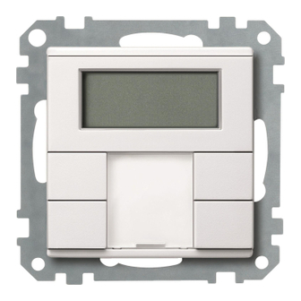
Push-button plus with room
temperature control unit
Operating instructions
A Push-button
B Cover
C Foil strip
D Safty screw
E Sticker (only push-button 4-gang)
System M
Push-button 2-gang plus with room
Connections, displays and operating
temperature control unit
elements
Art. no. MEG6212-03../MEG6212-04..
Lighting
ON
OFF
Blind
System M
9
Push-button 4-gang plus with room
temperature control unit
1
Art. no. MEG6214-03../MEG6214-04..
Present
Absent
3
Blind
Lighting
ON
OFF
5
Ventilation
7
Necessary accessories
1 - 8: Function keys
9 + 10: Function keys for display
– You have to complete the push-button plus 2-gang
A Display
with a design frame System M.
B LED
– You have to complete the push-button plus 4-gang
C IR receiver
with a design frame System M without central bridge
D Staus LED
piece(art. no. 4788.., 4858.., 4868.., 4878.., 5158..,
4888).
Getting to know the keypad
The push-buttons opposite each other can be config-
For your safety
ured as either individual push-buttons or a push-button
pair. The push-buttons are programmed with various
functions depending on the pre-setting.
¼
DANGER
For 4-gang push-button only:
Risk of fatal injury from electrical current.
The 4-gang push-button is equipped with an IR receiver,
The unit may only be installed and connected by
with which you can control the push-button with any IR
skilled electicians. Observe the regulations valid
remote control. Pressing push-buttons 1-8 on the remote
in the country of use, as well as the valid KNX
control activates the function of the corresponding push-
guidelines.
button. Push-buttons 9 and 10 of the remote control have
a direct effect on display push-buttons 9 and 10.
Getting to know the push-button
The push-button plus with room temperature con-
Mounting side
trol unit (reffered to below as the push-button) gives
you four (push-button 2-gang) or eight (push-button 4-
In order for the integrated room temperature control unit
gang) operating surfaces. The keys can be set individu-
to work in the best way, you should keep in mind the fol-
ally to perform various functions. Furthermore a room
lowing when selecting the right installation side:
temperature control unit is integrated, which allows you
to control temperature in various different ways.
Functions of the push-button:
– Switching, toggling, dimming, blind control
– Szenenfunktion
– Communication and disable functions
– Time control with synchronisation, reading external
temperature, fan control
Functions of the room temperature control unit:
– Heating/cooling with 1 controller output
– Heating/cooling with seperated controller outputs
– Heating/cooling with 2 controller outputs
The push-button can directly be connected to the KNX
and is parameterised by the electrical installer via the
KNX-Tool-Software (ETS).
Sources of interference
+
+
+
A
B
C
D
E
+
+
+
+
Mounting the push-button
Push-button 2-gang and 4-gang
1
2
A
10
9
10
B
2
1
2
4
3
Only push-button 4-gang
4
C
6
8
D
Operating the push-button
1 Set the push-button to programming state
2 Load the physical address and application from the
ETS into the push-button: The red programming
LED goes out.
Note for the electrician
|
Make sure that you note the settings you have
made in the ETS which are important for the user
in the configuration table (see „Pre-settings ta-
110...160 mm
ble"), because not all parameters that can be set
are shown in the display of the push-button.
Anti-theft protection
Push-button 2-gang and 4-gang
1
2
3
Dismantling the push-button
3
½
CAUTION
The device could become damaged.
Before removing the push-button, check whether
it is secured with protection against theft. Always
remove the protection against theft before remov-
ing the push-button.
Labbelling the push-button
Opening the labelling field
=
1
Creating labelled foil strips
You can also create and print corresponding foil strip
templates with any layout program.
Size specifications for foils (in mm):
Push-button Height
Width
2-gang
24,9
23
4-gang
96,2
23
Consult the operating instructions of your printer to find
out which type of foil strips you can print.
Only use the coloured foil strips enclosed as the
|
base, since this ensures that the push-button
LEDs under the labelling field can shine through.
Two versions of coloured foil strips are provided:
|
one with a recess in the middle for the IR receiver,
and one without a recess. If you want to control
the push-button via an IR remote control, you
have to use the coloured foil strip with recess. Al-
ways only use one of the two coloured foil strips.
Closing the labelling field
1
Pre-settings
When installing the push-button, the electrician defines
various settings that are necessary so you can use the
push-button correctly. Most of the explanations provided
on the following pages depend on these settings. The
electrician enters the settings in question in a table for
you (see table „pre-settings").
If you come across this symbol
|
it means that you can look up the corresponding
value in the table.
Preface room temperature control unit/
display
With the integrated room temperature control unit, you
can control the temperature in various different ways.
You can read and set important information on the dis-
play:
• Setpoint temperature
• Operating mode (comfort, standby, night, etc.)
• Working day/holiday
• Display mode (setpoint temperature, actual tempera-
ture, date etc.)
• Background lighting
• Setting the time/switching time
Getting to know the display
2
You will see the following symbols on the display:
Comfort mode or working day. The room tem-
perature is adjusted to the set comfort setpoint
temperature
.
The flashing symbol means that the comfort ex-
tension is active.
Standby mode or holiday. The room tempera-
ture is adjusted to the set standby setpoint tem-
perature
.
Night operation. The room temperature is ad-
justed to the set night setpoint temperature
Time control is active.
Constant display: The time has been synchro-
Thickness
nised.
max. 0,15
Flashing display: The time has not been syn-
max. 0,15
chronised; the displayed time may not be accu-
rate.
Alarm, symbol flashing. For 4-gang push-but-
ton: Additional acoustic warning sound possi-
ble
.
1 2 3 4
Weekday display
.
5 6 7
In combination with
: Fan speed
Menu command „Setting the background light-
ing" is activated.
Fan.
Heating control mode is active or controller re-
quires power.
Cooling control mode is active or controller re-
quires power.
Display under „Heating" or „Cooling" symbol.
- For heating or cooling:
2
„1": Setpoint temperature has not yet been
reached. The controller is heating or cooling.
„2": Level 2 is activated (display only if two-step
heating/cooling is set.
- For heating and cooling: Two modes are avail-
able: Manual or automatic
°C
Temperature display in degrees Celsius
°F
Temperature display in degrees Fahrenheit
88:88 Time display or value display
Getting to know the control menu
There is a control menu for selecting the individual func-
tions of the room temperature controller.
A rocker is integrated in the cover of the display. It has
three contacts: left, centre and right. With these push-
buttons, you can access the control menu, scroll back-
wards and forwards and change individual values.
when reading,
Overview of the menu structure
Setpoint
Operation mode
temperature
Workday/
leisure day
Standard Display
(current temp.)
Display mode
t2.1 ... t2.4
t1.1 ... t1.4
Time/
Display backlight
switching time
edit hour
edit minutes
Push-button action
Function triggered
Center –
Select menu
Long push-button action*
Save
Return to standard display
Center –
Short push-button action** Select next menu com-
mand
Left/Right –
Short push-button action** Change value
*Long push-button action = approx. 5 s
**Short push-button action = approx. 1 s
If you don't press any push-button within a period
|
of about one minute, the room temperature con-
.
trol unit automatically returns to the standard dis-
play. The values that were set before the control
menu was opened are restored; any changes
that you may have made are not saved. Ex-
ception: The temperature is saved directly.
Advertisement
Table of Contents

Summary of Contents for merten MEG6212-04 Series
- Page 1 Push-button plus with room temperature control unitKapitel3:Taster3.1Taster Plus© Merten2005V6212-581-0009/09 Scope of delivery Sources of interference Getting to know the control menu Anti-theft protection Pre-settings There is a control menu for selecting the individual func- When installing the push-button, the electrician defines tions of the room temperature controller.
- Page 2 Setting the operating mode Setting the display mode Setting the internal clock time and switching times Setting the room temperature control Other display views Technical data unit/display view APL. Application not loaded or faulty Power supply: via KNX With the display mode, you can select which val- If the time is updated by an external time switch, Heating setpoint temperature = cooling setpoint Connection:...
-
Page 3: Application Overview
Range name: Multifunction with RTCU and FanCoil 1817/1.0 Media type: Twisted Pair Product name: Push-button, 4-gang plus, room temp. control + IR Order number: MEG6214-40xx, MEG6214-41xx The application can only be operated with ETS3. © 2009 Merten by Schneider Electric... -
Page 4: Function Overview
Base = 1 second * factor = 3 gives 3 seconds. For further details about time control, synchronisation The bold values in a table are the values set dur- and the master-slave function, see the "Time control" ing factory configuration. chapter. © 2009 Merten by Schneider Electric... -
Page 5: Start-Up Delay
You can also set the persistence pe- riod and the brightness of the background lighting. The parameters for the background illumination and display mode can be changed using the menu buttons on the push-button (see operating instruc- tions). © 2009 Merten by Schneider Electric... - Page 6 40.0 °C = 104.0 °F, 20.0 °C = 68.0 °F Report if actual temperature is 0.0 = 32.0 °F to lower than 19.0 °C = 66.2,0 °F, 3.0 °C = 37.4 °F © 2009 Merten by Schneider Electric...
-
Page 7: Communication Objects
100 %, 90 %, 80 %, ..., 0 %, 25 %, 75 % 255, 254, 253, ...0 Value 2 0 %, 10 %, 20 %, ... 100 %, 25 %, 75 % 0, 1, 2, 3, ... 255 © 2009 Merten by Schneider Electric... - Page 8 Flashes when switch/value object B equals 0 Flashes when status feedback object equals 1 Flashes when status feedback object equals 0 Operation = flash / release = OFF Long operation = flash / release = OFF © 2009 Merten by Schneider Electric...
- Page 9 4-bit dimming object; the parameters for the dimming steps can be set. You can also transmit the relevant dimming step cyclically for a period of time which can be set as required. © 2009 Merten by Schneider Electric...
- Page 10 1/16 brighter ceive 1/32 brighter Push-button X Status feedback 1 bit Low WC Receive 1/64 brighter object Step dimming (darker) To min. brightness 1/2 darker 1/4 darker 1/8 darker 1/16 darker 1/32 darker 1/64 darker © 2009 Merten by Schneider Electric...
-
Page 11: Blind Control
Both push-buttons must be given the same group addresses. Parameter Setting Long operation time equals 4 - 250, 6 100 ms * factor (4-250) Direction of movement, blind Down © 2009 Merten by Schneider Electric... - Page 12 Flashes when status feedback object equals 0 Operation = flash / release = OFF Push-button Slat position 1 byte Low CT Transmit Long operation = flash / release = OFF Push-button Status feedback 1 bit Low WC Receive object © 2009 Merten by Schneider Electric...
- Page 13 100 %, 90 %, 80 %, ..., 0 %, Sends value 1 25 %, 75 % Sends value 2 255, 254, 253, ...0 Action at release Sends 1 Sends 0 Toggles Sends its value None Sends value 1 Sends value 2 © 2009 Merten by Schneider Electric...
- Page 14 Value 1 = 255 eration) Value 2 = 50 Long operation time equals 4 - 250, 6 Sends value 1 / Sends value 2 Toggles / None 100 ms * factor (4-250) Number of objects Object A © 2009 Merten by Schneider Electric...
- Page 15 0.1 s, 1 s, 1 min, 1 h, 1 day value by 1 Factor (3-255) 3-255, 10 Cyclically reduce the current object value by 2 None (stops cyclical sending) No change None (stop after current cycle time) © 2009 Merten by Schneider Electric...
- Page 16 No action is currently carried out, but any active cycle time is not stopped. It runs through until the end, and then transmits the corresponding value. © 2009 Merten by Schneider Electric...
- Page 17 Object B Switch ac- tuator, re- Object A T 2 = Short cycle time T 3 = Long cycle time Object B Switch ac- tuator, re- T 1 = Staircase timer period © 2009 Merten by Schneider Electric...
- Page 18 (re- Push-button X Object A/B 1 byte Low WCT Transmit/ ceiving) receive Push-button X Status feedback 1 bit Low WC Receive Reaction object T 4 = Cycle time T 5 = Monitoring time © 2009 Merten by Schneider Electric...
- Page 19 0,01, ... 327,68; 0,01 ets) Factor (0-2047) 0 - 2047, 2000 Value 1 (-32768 - 32767) -32768...32767, 32767 Value 2 (-32768 - 32767) -32768...32767, -32768 Value 1 (0-65535) 0-65535, 65535 Value 2 (0-65535) 0-65535, 0 © 2009 Merten by Schneider Electric...
- Page 20 2 byte Low WCT Transmit/ A description of the actions is given below: receive • Sends [value]: Push-button X Status feedback 1 bit Low WC Receive Transmits the current value and stops a cyclical trans- object mission. © 2009 Merten by Schneider Electric...
- Page 21 Reduce the current object value once by the parame- terised step value. Any active cycle time is terminated. • Reverse slide direction and send cyclically: If no cycle time is running, the slide is pushed in the © 2009 Merten by Schneider Electric...
- Page 22 • No change: No action is carried out, and any active cycle time is continued. Keeping within the limits and toggling to a new slide direction are only possible with local, on-site operation! © 2009 Merten by Schneider Electric...
- Page 23 Operation = flash / release = OFF Number of objects Long operation = flash / release = OFF From object A From object B Flashes when object A not equal to 0 Flashes when object B not equal to 0 © 2009 Merten by Schneider Electric...
-
Page 24: Change Setpoint
Flashes when obj. setpoint adjustment equals 0 Flashes when status feedback object equals 1 Flashes when status feedback object equals 0 Operation = flash / release = OFF Long operation = flash / release = OFF © 2009 Merten by Schneider Electric... - Page 25 Operation = flash / release = OFF Switched on in comfort extension opera- tion Switched on in comfort operation Switched on in standby operation Switched on in night operation Switched on in frost/heat protection oper- ation © 2009 Merten by Schneider Electric...
- Page 26 Lock push-button 7 Lock push-button 8 Communication objects Include menu buttons in the lock You can select the following communication objects: Function Object name Type Prio Flags Behaviour Disable Locking object 1 bit Receive function © 2009 Merten by Schneider Electric...
- Page 27 Value 3 sending No telegram Value 4 sending 0 % - 100 % Value 5 sending 0-254 Value 6 sending Value 8 sending Switch on with priority (11) Switch off with priority (10) Remove priority (00) © 2009 Merten by Schneider Electric...
- Page 28 The function "Request time synchronisation via the bus" only works in conjunction with an appro- priate year time switch. General Parameter Settings Receive date and time In one communication object In two communication objects © 2009 Merten by Schneider Electric...
- Page 29 • Switching time 2 = 12:00 Base (possible values in brackets) 0.01, ... 327.68, 0.01 Factor (0-2047) 0-2047, 1000 • Switching time 3 = 18:00 Select scene address internally 0-63, No • Switching time 4 = 22:00 © 2009 Merten by Schneider Electric...
- Page 30 1 bit/1 byte status objects, taking into account a temperature which has been measured separately, temperature drop de- tection, and valve protection. © 2009 Merten by Schneider Electric...
- Page 31 Comfort = 21 °C Comfort = 26 °C Standby = 19 °C Standby = 19 °C Night = 17 °C Night = 17 °C Frost protection = 7 °C Frost protection = 7 °C © 2009 Merten by Schneider Electric...
- Page 32 Comfort = 21 °C Comfort = 28 °C Standby = 19 °C Standby = 26 °C Night = 17 °C Night = 24 °C Frost protection = 7 °C Frost protection = 7 °C © 2009 Merten by Schneider Electric...
-
Page 33: Comfort Mode
Current object values Communication objects You can select the following communication objects: Function Object name Type Prio Flags Behaviour Control Comfort exten- 1 bit Receive sion input Control Comfort exten- 1 bit CRT Transmit sion output © 2009 Merten by Schneider Electric... -
Page 34: Standby Operation
Comfort operation Operation mode after reset Comfort operation Standby operation Standby operation Night operation Night operation Frost/heat protection Frost/heat protection Last operation Operation mode after download Comfort operation Standby operation Night operation Frost/heat protection operation © 2009 Merten by Schneider Electric... -
Page 35: Dewpoint Alarm
If the window contacts are monitored and the windows are only closed after the away setting is ac- Comfort mode tivated, the frost/heat protection remains active anyway. Night mode Standby mode © 2009 Merten by Schneider Electric... - Page 36 Standby mode Frost/heat Disable object protection Frost/heat protection object Temperature jump detection Comfort Operation Comfort Menu extension mode object object object Comfort extension Frost/heat protection Comfort mode 1, 2, 3 Night mode Standby mode © 2009 Merten by Schneider Electric...
-
Page 37: Heating And Cooling
"0". Cooling with constant correcting variables (e.g. EMO valve drive): • Cooling ceiling • Air convectors Cooling with switching correcting variables (e.g. switch actuator): • Cooling ceiling • Air convectors © 2009 Merten by Schneider Electric... - Page 38 "0 K". The air conditioning unit cools immediately be- cause the setpoint for cooling has been exceeded. The procedure repeats itself again and again. This error is displayed as "Er 2" in the display. © 2009 Merten by Schneider Electric...
- Page 39 Room temperature (°C) The push-button displays the active basic level with a "1" and the active additional level with a "2". © 2009 Merten by Schneider Electric...
-
Page 40: Controller Types
To counteract this effect, you can set a sufficiently small hysteresis. However, this leads to an increase in switch- ing frequency, and therefore to increased wear of the drives. © 2009 Merten by Schneider Electric... - Page 41 (min) control conditions in the room. Correcting variable t (min) When the setpoint temperature changes, the controller recalculates the required correcting variable and trans- mits it still within the current cycle (broken line). © 2009 Merten by Schneider Electric...
- Page 42 Temperature limitation using shading facility: Characteristics Parameter Setting Cooling only Controller type Cooling Correcting variable out- Switching 2-step control put - heating Hysteresis Large (e.g. 2 K) © 2009 Merten by Schneider Electric...
- Page 43 Switch between heating and Automatically (via the controller) cooling Externally (via heating/cool- ing object) Heating/cooling read request after bus voltage recovery Waiting time after switching-over (heating/cooling) Waiting time (1-60 min) 1 ... 60, 10 © 2009 Merten by Schneider Electric...
-
Page 44: Setting The Setpoints
Night = 17 °C Night = 20 °C to the set weighting. The "Current actual temperature Frost protection = 7 °C Frost protection = 7 °C input" object is then overwritten by the calculated actual value. © 2009 Merten by Schneider Electric... - Page 45 0.3 K - 2.0 K, 0.5 K Frost protection during heating operation Heat protection during cooling operation Temperature measurement Of actual internal temperature Of actual external temperature Of actual internal or external tem- perature Of (resulting) internal temper- ature © 2009 Merten by Schneider Electric...
- Page 46 1-60, 30 variable in min (1-60) Send inactive correcting variable cyclically Use valve protection Activate valve protection every ... days (1 - 30) 1-30, 15 Approach end position for ... min (1-30) 1-30, 4 © 2009 Merten by Schneider Electric...
-
Page 47: Communication Objects
Status (controller in- 1 bit Low CRT Transmit/ active) read out Control Status (frost alarm) 1 bit Low CRT Transmit/ read out Control Heating status (basic 1 byte Low CRT Transmit/ level) read out © 2009 Merten by Schneider Electric... - Page 48 Communication objects You can select the following communication objects: Function Object name Type Prio Flags Behaviour Display exter- External tempera- 2 byte Low WCT Transmit/ nal tempera- ture receive ture © 2009 Merten by Schneider Electric...
- Page 49 Behaviour on bus voltage recovery / bus voltage failure Behaviour on bus voltage recovery / bus Merten GmbH voltage failure Merten GmbH, Solutions for intelligent buildings, Serv- ice Center, Fritz-Kotz-Str. 8, Industriegebiet Bomig- Behaviour on application/recovery of the bus volt- West, D-51674 Wiehl...
Need help?
Do you have a question about the MEG6212-04 Series and is the answer not in the manual?
Questions and answers