
Related Manuals for Elinx EIR405-T

Summary of Contents for Elinx EIR405-T
- Page 1 Manual Documentation Number EIR405-T – 0109m www.bb-elec.com www.bb-europe.com...
- Page 2 All Brand names used in this manual are the registered trademarks of their respective owners. The use of trademarks or other designations in this publication is for reference purposes only and does not constitute an endorsement by the trademark holder Manual Documentation Number EIR405-T – 0109m www.bb-elec.com...
-
Page 3: Table Of Contents
Wiring the Power Inputs ............................4 Wiring the Fault Alarm Contact .........................5 LED Indicators ..............................6 Ports..................................6 Cabling................................8 Mounting Installation ............................11 DIN-Rail Mounting............................11 Wall Mount Plate Mounting ..........................13 Hardware Installation ............................14 Installation Steps.............................14 Troubleshooting ..............................16 Technical Specification...........................17 Manual Documentation Number EIR405-T – 0109m www.bb-elec.com www.bb-europe.com... -
Page 4: Overview
Dual Power Input To reduce the risk of power failure, the EIR405-T provides two 12 to 48 VDC power inputs. If the power fails, the switch will automatically switch to the secondary power input. Also if the power goes out the corresponding P1 or P2 LED will go out and the Fault LED will light. -
Page 5: Features
• Provides flexible mounting: DIN-rail or Panel Mounting • Supports operating temperatures from -40 to 75 Packing List • (1) EIR405-T, 5 Port Gigabit Industrial Ethernet Switch • (1) Quick Start Guide • (1) CD ROM with User Manual • (2) Wall Mounting Bracket and Screws Manual Documentation Number EIR405-T –... -
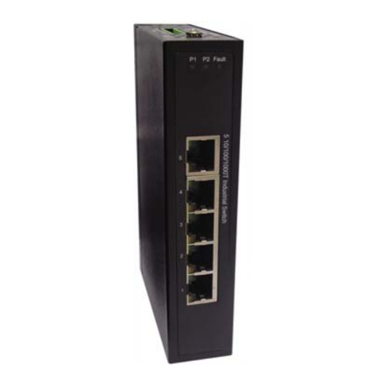
Page 6: Hardware Description
Hardware Description Hardware Description Front Panel The Front Panel view of the EIR405-T is shown below. Manual Documentation Number EIR405-T – 0109m www.bb-elec.com www.bb-europe.com... -
Page 7: Top View
Hardware Description Top View The top panel view of the EIR405-T is equipped with one terminal block connector that consists of two 12 to 48 VDC power inputs and the fault alarm output. Wiring the Power Inputs Follow the steps below to insert the power wires. -
Page 8: Wiring The Fault Alarm Contact
If one of the power sources fails a fault will be detected causing the circuit to open. Insert the wires into the fault alarm contact (No. 3 & 4) Note The wire gauge for the terminal block should be 12 to 24 AWG. Manual Documentation Number EIR405-T – 0109m www.bb-elec.com www.bb-europe.com... -
Page 9: Led Indicators
Hardware Description LED Indicators Below is a table that explains the status of each the power and network status LED’s found on the front panel of the EIR405-T. Color Description Power input 1 is active Green Power input 1 is inactive... - Page 10 Note “+” and “-” signs represent the polarity of each wire pair. All ports on the EIR405-T support automatic MDI/MDI-X operation, you can use straight-through cables (See Figure below) for all network connections to PCs or servers, or to other switches or hubs. In straight-through cables, pins 1, 2, 3, and 6, at one end of the cable, are connected straight through to pins 1, 2, 3 and 6 at the other end of the cable.
-
Page 11: Cabling
10Mbps: Use category 3, 4, 5 or greater cable 100Mbps: Use category 5 or greater 1000Mbps: Use category 5e or greater cable Cable distances should be less than 100 meters (328 ft.) long. Manual Documentation Number EIR405-T – 0109m www.bb-elec.com www.bb-europe.com... - Page 12 Hardware Description Manual Documentation Number EIR405-T – 0109m www.bb-elec.com www.bb-europe.com...
- Page 13 Hardware Description Manual Documentation Number EIR405-T – 0109m www.bb-elec.com www.bb-europe.com...
-
Page 14: Mounting Installation
Then follow the steps below to hang the switch onto a DIN rail. Rear Panel of the switch DIN-Rail 1. Use the screws to screw the DIN rail clip onto the switch. 2. To remove the DIN rail clip, reverse step 1. Manual Documentation Number EIR405-T – 0109m www.bb-elec.com www.bb-europe.com... - Page 15 4. Then, lightly push the bottom of the switch so it can snap the rest of the way onto the DIN rail track. 5. Check that the switch is held tightly to the DIN rail track. Manual Documentation Number EIR405-T – 0109m www.bb-elec.com www.bb-europe.com...
-
Page 16: Wall Mount Plate Mounting
Use the screws to screw the wall mount plate onto the switch. Use the hook holes at the corners of the wall mount plates to hang the switch on the wall. To remove the wall mount plate, reverse steps above. Manual Documentation Number EIR405-T – 0109m www.bb-elec.com www.bb-europe.com... -
Page 17: Hardware Installation
Hardware Installation Hardware Installation The diagram below shows a typical switch installation for the EIR405-T. Installation Steps Unpack the switch. Check that the DIN rail is screwed onto the switch. If the DIN rail clip is not screwed onto the switch. Please refer to DIN-Rail Mounting section for DIN-Rail installation. If you want to wall or panel mount the switch, then please refer to Wall or Panel Mount Plate Mounting. - Page 18 Industrial switch will light up when the cable is connected to the network device. Please refer to the LED Indicators section for LED light meaning. When all connections are made and the LED lights show normal activity the installation is complete. Manual Documentation Number EIR405-T – 0109m www.bb-elec.com www.bb-europe.com...
-
Page 19: Troubleshooting
• If the switch LED’s represent normal operating mode and the cable connections are correct and no data is transmitted or received through the switch, contact your Network Administrator for network configuration and status help. Manual Documentation Number EIR405-T – 0109m www.bb-elec.com www.bb-europe.com... -
Page 20: Technical Specification
2 x Unregulated 12 to 48 VDC Fault Output 1 Relay Output Mechanism Dimensions (WxDxH) 30 x 95 x 140 mm (1.2 x 3.7 x 5.5 inches) Enclosure IP30, Metal shell with solid mounting kits Manual Documentation Number EIR405-T – 0109m www.bb-elec.com www.bb-europe.com... - Page 21 CE EN61000-4-2 (ESD) CE EN61000-4-3 (RS) CE EN61000-4-4 (EFT) CE EN61000-4-5 (Surge) CE EN61000-4-6 (CS) CE EN61000-4-8 CE EN61000-4-11 CE EN61000-4-12 CE EN61000-6-2 CE EN61000-6-4 IEC60068-2-32 Free Fall Shock IEC60068-2-27 IEC60068-2-6 Vibration Manual Documentation Number EIR405-T – 0109m www.bb-elec.com www.bb-europe.com...
Need help?
Do you have a question about the EIR405-T and is the answer not in the manual?
Questions and answers