
Summary of Contents for MaxTronic JanusRAID SA-6692J
- Page 1 JanusRAID SA-6692J Hardware User Manual 42-30000-5067 SATA II JBOD enclosure Version 1.1...
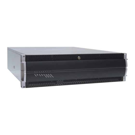
- Page 3 SA-6692J SATA II JBOD enclosure Hardware User Manual...
-
Page 5: Table Of Contents
Table of Contents Preface........................i Chapter 1 System Requirements Operating Environment ..................1 Host Interface-x4 SAS Channel ............... 1 Hard Disk Interface-SATA II ................1 Chapter 2 Basic Configuration Unpacking ......................3 Components ......................4 Closed Front Panel ................... 4 Open Front Panel ..................... -
Page 7: Preface
No part of this documentation may be reproduced in any form by any means with- out prior written authorization of MaxTronic International Co., Ltd. and its licensors, if any. - Page 8 SA-6692J SATA II JBOD enclosure System Important Safety Instructions, Care and Handling Before starting, take a few minutes to read this manual. Read all of these instructions and save this manual for later reference. Protect the disk array system from extremely high or low temperatures.
- Page 9 SA-6692J SATA II JBOD enclosure System The appliance must be grounded. The disk array system is equipped with a 3-wire grounded type of power cord. This power cord will only fit into a grounded type of power outlet. If an extension cord or a power center is used with the disk array system, make sure that the total current con- sumption of all products plugged into the wall outlet does not exceed the ampere rating.
- Page 10 SA-6692J SATA II JBOD enclosure System Placement Notes • The disk array system LCD panel can be damaged by exposure to direct sunlight. Limit exposure to subdued or indirect sunlight only. • The disk array system should be used only in clean environments that are free from airborne contaminants such as dust, dirt, and smoke.
-
Page 11: Chapter 1 System Requirements
1 System Requirements Ensure that the following requirements are met before installing the disk array system. Operating Environment • 15 cm (6-inches) of space around the disk array system for proper ventilation • ambient temperature of 5°C to 40°C (40°F to 104°F) •... -
Page 13: Chapter 2 Basic Configuration
2 Basic Configuration This chapter describes system connections and disk installation. Unpacking Contact your supplier if any of the following items are missing or damaged. Caution The system is heavy. Be careful when lifting and moving it. Front Panel Keys Hardware user Manuals System Rails... -
Page 14: Components
SA-6692J SATA II JBOD enclosure System Components Closed Front Panel Name Description • Green - System power supplies are installed and working properly Power • Red - This system has a faulty power supply • Green - Fan modules are installed and working properly •... -
Page 15: Open Front Panel
SA-6692J SATA II JBOD enclosure System Open Front Panel 1 2 3 4 5 6 7 8 9 10 11 12 13 14 15 16 Tray LED Indication Color Status Bule Access Green Disk Online No Disk Name Description 1-16 Disk trays 1-16 Removable hot swap disk trays Front panel door... -
Page 16: Disk Tray
SA-6692J SATA II JBOD enclosure System Disk Tray Front Name Description Power/Error indicator LED Different colors indicate different disk states: • Green – Disk online • Orange – Disk fail • Red – No disk This blue LED indicates that the disk is being Access indicator LED accessed. -
Page 17: Rear View
SA-6692J SATA II JBOD enclosure System Rear View Name Description Cooling fan 1 System cooling fan. Expansion Port Used for JBOD expansion. Host Channel 1 Connects to EXP port on RAID system or SAS HBA card. Host Channel 2 Connects to EXP port on RAID system or SAS HBA card. -
Page 18: Installing Disks
SA-6692J SATA II JBOD enclosure System Installing Disks This section describes how to install disks in the system. 1 Unlock the front panel door, then pull it open. Tray LED Indication Color Status Bule Access Green Disk Online No Disk 2 Push the button (A) to release the disk tray handle. - Page 19 SA-6692J SATA II JBOD enclosure System 5 Slide the disk tray back into the empty slot (A), then slowly close the disk tray handle (B). 6 Repeat steps 2 to 5 until all of the required disks have been installed 7 Push the front panel door closed, and lock it.
-
Page 20: Making Connections
SA-6692J SATA II JBOD enclosure System Making Connections After the required number of disks have been installed, follow the instructions for your configuration. Connecting to a host of RAID system or HBA Use a x4 external SAS cable (SFF-8088 to SFF-8088) to connect the CH1(A) port on your SA-6692J to a EXP(B) port on the RAID system, or connect a x4 SAS (C) (SFF- 8088) port on HBA card. -
Page 21: Expanding Additional Jbod Enclosure
SA-6692J SATA II JBOD enclosure System Expanding additional JBOD enclosure Use a x4 external SAS cable continue to connect the EXP(A) port of previous SA-6692J to the CH1(B) port of the next SA-6692J. Note • It can expand up to THREE of SA-6692J to a single RAID system. RAID System SA-6692J-1 SA-6692J-2... -
Page 22: Connecting And Turning On The Power
SA-6692J SATA II JBOD enclosure System Connecting and Turning on the Power 1 Plug a power cable (A) to a power connector at the rear of the unit, then plug the second power supply cable into the second power connector (B). Note The system is equipped with auto switching power supplies that can run on 100 to 240 VAC. -
Page 23: Mounting In A Rack
SA-6692J SATA II JBOD enclosure System Mounting in a Rack When the system is completely set up, it can be installed in a standard 19-inch rack. Fol- low the instructions in this section to install the system in a rack. 1 Clip eight rack nuts supplied with your rack, into the rack, taking care that they correspond with the mounting points on the rails. -
Page 24: Installing The Rail Extenders
SA-6692J SATA II JBOD enclosure System Installing the Rail Extenders Follow these instructions to fit the rail extenders if required. 1 If required, bolt the rail extenders into place as shown using the small bolts pro- vided. 2 Slide the system into the rack and bolt it into place with the supplied fixing screws. -
Page 25: Chapter 3 Maintenance Replacing A Disk
3 Maintenance Replacing a Disk A disk failure is indicated when the LED at the front of the drive tray turns red . Disks are hot swappable, which means that they can be inserted and removed while the disk array system is powered on and operating. Follow these instructions to replace a failed disk. -
Page 26: Replacing A Power Supply
SA-6692J SATA II JBOD enclosure System Replacing a Power Supply Power supplies are hot swappable, which means that they can be inserted and removed while the system is powered on and operating. Follow these instructions to replace a failed power supply. 1 Identify the power supply that has failed. -
Page 27: Replacing A Fan Module
SA-6692J SATA II JBOD enclosure System Replacing a FAN module A FAN module failure is indicated when the Fan LED at the front of the drive tray turns red and the audible alert sounds. Follow these instructions to replace a failed FAN module. 1 Identify the FAN module that has failed, loosen the retaining screws, slide it out of chassis. -
Page 29: Appendix
Appendix Hardware Specifications Item Specification Host Interface SAS x 2 Expanding Port SAS x 1 Dimensions 132 mm (H) x 485 mm (W) x 565 mm (D) Weight 24 Kg without disks Enclosure Monitoring • LED indicator • In-band SES •...
Need help?
Do you have a question about the JanusRAID SA-6692J and is the answer not in the manual?
Questions and answers