
Summary of Contents for SuperOn SER-H410A
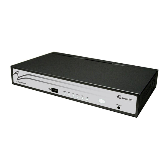
- Page 1 User Manual SER-H410A v1.0 ○ SER-H410A 4CH H.264 DVR This document contains preliminary information and subject to change without prior notice.
- Page 2 WARNING Cautio TO REDUCE THE RISK OF FIRE OR RISK OF ELECTRIC SHOCK DO NOT OPEN ELECTRIC SHOCK, DO NOT EXPOSE THIS APPLIANCE TO RAIN OR MOISTURE. CAUTION: TO REDUCE THE RISK OF ELECTRIC SHOCK, DO NOT REMOVE COVER (OR BACK). NO USER SERVICEABLE PARTS NOTE: This equipment has been tested INSIDE.
-
Page 3: Table Of Contents
Table of Contents CHAPTER 1 PACKING DETAIL AND INSTALLATION............5 1-1 PACKING ........................5 1-2 Hard Disk Installation ....................6 CHAPTER 2 PANEL LOCATION....................8 2-1 FRONT PANEL CONTROLS ..................8 2-2 4CH REAR PANEL CONNECTORS................9 CHAPTER 3 LIVE, PLAYBACK AND PTZ OPERATIONS ........... 10 3-1 LIVE Mode........................ - Page 4 8-1.2.1 Add New Login DVR ______________________________________________ 49 8-1.2.2 Logging Onto the DVR _____________________________________________ 49 8-1.2.3 Modify the Login Information of DVR ________________________________ 50 8-1.2.4 Delete the Login Information of DVR ________________________________ 50 8-1.3 Live Monitoring Operation _______________________________________ 51 8-1.3.1 Scroll the Image ___________________________________________________ 51 8-1.3.2 Image Quality Setup ________________________________________________ 51...
-
Page 5: Chapter 1 Packing Detail And Installation
CHAPTER 1 PACKING DETAIL AND INSTALLATION 1-1 PACKING 1. DVR 3. IR Remote Controller 2. Quick Start 4. Batteries x2 *Please press “DVR1” button before operation 5. CD 6. SATA Cord x1 7. Screws x4 8. Power Adaptor 9. Power Cord... -
Page 6: Hard Disk Installation
1-2 Hard Disk Installation Step 1) Remove the 3 screws from DVR as cycled below. Step 2) Remove the front cover from DVR as indicated by the arrow. Step 3) Place the HDD on the HDD plate and connect the power and the SATA cables. - Page 7 Step 4) Screw the bottom of the DVR as indicated as cycled. Step 5) Place the bottom of DVR and screw.
-
Page 8: Chapter 2 Panel Location
CHAPTER 2 PANEL LOCATION 2-1 FRONT PANEL CONTROLS ○ ○ ○ ○ ○ ○ ○ ○ ○ Port for USB external devices. USB 2.0 Port ○ DVR Power is on. Power LED Display- ○ Hard disk is in use. LED Display - ○... -
Page 9: 4Ch Rear Panel Connectors
2-2 4CH REAR PANEL CONNECTORS ③ ○ ○ ○ ○ ○ ○ ○ ○ ⑩ ○ Socket for a DC 12V input. DC 12V BNC port to display full screen image of all installed cameras in ○ SPOT monitor sequence. ○... -
Page 10: Chapter 3 Live, Playback And Ptz Operations
CHAPTER 3 LIVE, PLAYBACK AND PTZ OPERATIONS 3-1 LIVE Mode You can monitor all the channels, listen to audio signal and have some related operations under LIVE mode. This paragraph describes the IR remote controller, mouse operation and on screen graphical icons under LIVE mode. - Page 11 Table 3-1.2 Graphical icons that will display after right-clicking your mouse under LIVE mode. Icon Description Resting the cursor on this icon will bring up the following four menu icons. Main MENU SEARCH menu BACK-UP menu PTZ mode Turn on/off recording. Playback.
- Page 12 Table 3-1.3 Description of on screen graphical icons in LIVE mode Icon Description Recording is on LIVE Audio is on LIVE Audio is off Motion detected on the channel Sensor triggered on the channel Video loss detected on the channel USB device detected Remote user currently logging into DVR.
-
Page 13: Playback Mode
3-2 PLAYBACK Mode Switch to PLAYBACK mode by pressing “PLAY” under the LIVE mode, the graphical icon will show up on the upper center of the screen and the operation panel ( see below picture) will show up at right lower corner of the screen. You can drag the panel by mouse to place it on any location of your screen. - Page 14 Table 3-2.2 The mouse operation under the PLAYBACK mode. Icon Description 「 」 Fast rewind 「 」Fast forward Play / pause 「▲ / SLOW」 ,slow playback 「▼ / ■」stop 「 ▌▌」pause playback Full screen display Quad display...
-
Page 15: Ptz Mode
3-3 PTZ Mode Switch to the PTZ mode by pressing “PTZ” button under the LIVE mode. The PTZ icon will appear on upper left of the screen. Table 3-3.1 Remote Controller functions under the PTZ mode Description Button / SLOW Move PTZ up. - Page 16 Table 3-3.2 Mouse operation under the PTZ mode Icon Description Leave PTZ Mode, back to the LIVE mode. Pre-set number N.(1~64) Go to pre-set number N. Set PTZ at N. 「TOUR」pre-set locations in order. Set current location as the beginning for patrol line scan.
-
Page 17: Chapter 4 Main Menu Setup
CHAPTER 4 MAIN MENU SETUP To enter the main menu and set up DVR, log-in account and user password are required. The default password of the administrator is “123456”. Please check the “Account Setup” for related setup of other log-in users. Table 4-0.1 Some definitions of virtual keyboard. -
Page 18: Record Setup
Table 4-0.2 The operation of remote controller under the setting menu Item Description Switch to different options under one item Switch to different items MENU Save setup and back to LIVE mode Back to Upper level of the menu ENTER Enter the menu, or display virtual keyboard PS. -
Page 19: 4-1.1 Quality & Frame Rate Setup
4-1.1 Quality & Frame Rate Setup Item Description Resolution Choose record resolution from : CIF / HD1(2CIF) / D1. Record Type You can setup quality and FPS separately for record type. Check/uncheck the box will enable/disable recording of that channel. Quality Choose from Lowest/ Low/ Normal/ High/ Highest Choose recording frame rate. -
Page 20: 4-2.1 Motion Setup
4-2.1 MOTION SETUP Item Description Check the box to Enable/Disable Motion Detection for all Motion Detection channels. Check the box to Enable/Disable popup screen function for all Motion Popup channels. When motion is detected in LIVE mode, the detected channel image will pop up in full screen display. You can setup independently for each channel. -
Page 21: 4-2.1.1 Motion Area Setup
4-2.1.1 MOTION AREA SETUP The motion detection has been divided into 16x12 grids. The default detection area is full screen as it marked in transparent for local DVR and purple for remote access. Areas deselected for motion detection are marked in red for both local and remote site. Item Description LOCK/ZOOM... -
Page 22: 4-2.2 Sensor Setup
4-2.2 SENSOR SETUP Item Description Sensor Detection Check the box to Enable/Disable sensor detection for all channels. Sensor Popup Check the box to Enable/Disable popup screen function for all channels. When Sensor is detected in LIVE mode, the detected channel image will pop up in full screen display. Click or press ▼... -
Page 23: Schedule Setup
4-3 SCHEDULE SETUP Except from starting recording manually, you can also setup the recording time by weeks and schedule including normal, motion detect, and sensor detect recording type. Item Description Click or press ▼ to select Page. Each page provides 10 schedules Page for setup. -
Page 24: 4-3.2 Holiday Setup
4-3.2 Holiday Setup Since holidays are different by different country and region, you can setup the holiday of your location accordingly. 4-4 CAMERA SETUP Item Description You can setup independently for each channel. Mask Check the box to Enable/Disable mask function for LIVE mode Drag the white bar or press ◀... -
Page 25: Account Setup
4-5 ACCOUNT SETUP The Account Setup menu is used to provide role-based permission independently setting for each user (maximum of 4 users) to access DVR over network. The default admin account is 「admin」and password is “123456”. P.S The factory default admin password is 123456, it will not be changed along upgrading with new firmware. -
Page 26: 4-5.1 Permission Setup
4-5.1 Permission Setup The Account Setup is set to provide individual user (maximum of 4 users) role-based permissions, including access to Setup menu, Network operation, PTZ function, Playback, Utility, Backup. Password expiry date and Mask on specific channels while playing back. Can not be accessed if the password is expired…... -
Page 27: 4-6.1 Networking Setup
4-6.1 NETWORKING SETUP The DVR supports DHCP, LAN and ADSL accesses for network connection. 4-6.1.1 DHCP If the DHCP option is used for DVR network connection, an IP address is assigned by the DHCP server automatically. 4-6.1.2 LAN Select LAN for network connection, the following information is required. Item Description IP Address... -
Page 28: 4-6.1.3 Adsl
4-6.1.3 ADSL Select ADSL for network connection, the following information is required. Item Description User Name Enter user name provided by ISP Password Enter password provided by ISP 4-6.2 HTTP SETUP Item Description Enable HTTP Check to enable HTTP server. Users can remotely access into the Server DVR over the network if the HTTP function is activated. -
Page 29: 4-6.3 Ddns Setup
4-6.3 DDNS Setup Item Description Enable DDNS Check/Uncheck to enable/disable DDNS function. Enter the registered SMTP Server: DDNS Server DYNDNS.ORG、NO-IP.ORG、CUSTOM.COM、3322.ORG、 I-DVR.NET (Provided by our company, please refer to appendix for more information)* SMTP Server Enter the registered SMTP Server. User Name Enter user name. -
Page 30: Ptz & Rs485 Setup
Item Description Enable E-mail Check the box to enable/disable E-mal Notification function. Notification SMTP Server Enter to set up SMTP Server name. User Name Enter to set up User Name. Password Enter to set up Password. Sender E-mail Enter to set up e-mail address of receivers. E-mail address Enter to set up e-mail addresses for up to 10 receivers individually. -
Page 31: System Setup
4-8 SYSTEM SETUP Item Description DVR Name The name of DVR will be shown when users login from remote access. DVR Location The location of DVR will be shown when users login from remote access Click or press ▼ to select OSD language. Language ◀... -
Page 32: 4-8.1 Display Setup
4-8.1 DISPLAY SETUP Item Description Turn On / Off OSD display DVR Status Turn On / Off DVR illustration and record status display Date/Time Turn On / Off date and time display Channel Name Turn On / Off channel name display Set up the color of border in LIVE , PLAYBACK mode. -
Page 33: 4-8.2.1 Change Date & Time
Item Description Hour Format 12HOURS/ 24HOURS Date Format MM-DD-YY/DD-MM-YY/YY-MM-DD Date/Time Position Choose the position of Time and Date display Change Date & Time Setup time and date of DVR Time Zone Setup Set up GMT and Daylight Saving Time. Internet Time Setup Setup automatic synchronization with internet server 4-8.2.1 CHANGE DATE &... -
Page 34: 4-8.2.3 Internet Time Setup
4-8.2.3 INTERNET TIME SETUP Synchronize your DVR time with internet time server. Item Description Check to enable DVR automatic synchronization function. Automatic Effective by this option selected, DVR will automatically Synchronization synchronize the time upon rebooting or by every 24 hours after booting. -
Page 35: 4-8.4 Spot Setup
Item Description KEY TONE Enable/Disable keystrokes. Set relay signal to be Normal Close (N.C.) or Normal Open (N.O.). Relay Switch Connection Buzzer Duration Set up the duration from 1~999 seconds. Enable/Disable buzzer operation when the alarm is triggered for ALARM BUZZER sensor, motion and vloss (Video Loss). -
Page 36: Utility Setup
4-9 UTILITY SETUP Item Description Select to enter hard disk initialization menu. Please stop HDD Initialization recording before entering this menu. Enter the menu, system will show all the data (model ,volume ) of HDD that installed in DVR. Check the HDD you’d like to initialize then press “Start”. -
Page 37: Diagnostic
4-10 DIAGNOSTIC Item Description Version The current firmware version of DVR The connected IP address of DVR. If disconnected from IP Address network, the screen will display” NETWORK DISCONNECT”. MAC Address MAC Address of DVR HDD Volume The capacity of HDD HDD Used Rate Percentage of space used on HDD. -
Page 38: Chapter 5 Backup & Search
CHAPTER 5 BACKUP & SEARCH 5-1 BACKUP SETUP User can backup any segment of recorded data in a specified time frame. To do so, either a CD R/W or storage device, like USB, must be connected to the DVR. Recorded data can also backup into NB/PC through our remote access software: 「DVRemoteDesktop.exe」... -
Page 39: Search Setup
5-2 SEARCH SETUP Item Description Event Search Press to enter event search menu Time Search Press to enter time search menu 5-2.1 EVENT SEARCH The DVR automatically records events with type, time and channel information included. If there is recording data for an event, a yellow signal will be shown on the left side of time information. -
Page 40: 5-2.1.1 Criteria Setup For Event Search
Item Description Criteria Setup conditions of event search Page Convert pages of events Date/Time Date/time when event occurred. Event type, defined as following Video Loss VLOSS MOTION Motion Detected SENSOR Sensor Detected REMOTEIN user log-in over the network Event Type REMOTEOUT user log-out over the network POWER ON... -
Page 41: 5-2.2 Time Search
5-2.2 TIME SEARCH TIME SEARCH can search for the specific time of recording data to playback. Note that dates □ with recording data are marked with a red square “ “. System will start playing back according to the date you selected. Calendar will be shown by using mouse to click on “year” and “month”. -
Page 42: Chapter 6 Network Surveillance
CHAPTER 6 NETWORK SURVEILLANCE AP software:「DVR Remote Desktop」can allow you to remotely access and control the DVR from PC. 6-1 AP Software Installation and Setup Step One:Enter the IP address of DVR in IE browser Step Two: Windows as below will show up. Please enter the user name and password. Default user name and password is admin/123456. - Page 43 Step Three: Click on the link to start downloading the AP software. Step Four: Run or Save our AP software. Step Five: If you choose to run the software, Start window will be shown up. Please enter information of login DVR: IP, Port, Username and Password, or choose “Play Recorded File”...
-
Page 44: Ap Software Operation
Step Six: You’ve logged into the DVR 6-2 AP Software Operation Open the file “DVRemoteDesktop.exe”; enter the information of DVR “IP address”, “Port” “Username” and “Password” and click “OK”. You should be able to login DVR successfully and start to use the software. The default username and password is 「admin/ 123456」 “DVRemoteDesktop.exe”... - Page 45 Table 6-2.2 System Requirements for AP software Intel Pentium 4 above Microsoft Windows Vista、Windows XP SP2 above Needed to support DirectX9.0 (Above) Note 1 Others DirectX 9.0 above Note 1: Known VGA card that support DirectX9.0 currently: NVIDIA: Geforce FXseries, Geforce 6series, Geforce 7series, Geforce 8series, Geforce 9series, Geforce 200series, etc.
-
Page 46: Chapter 7 Specificaitons
CHAPTER 7 SPECIFICAITONS 1. VIDEO Input Level 1.0 Vp-p±10% Composite, 75Ω Balanced NTSC 120 FPS Display Speed 100 FPS NTSC 720(H) X 480(V) Display Resolution 720(H) X 576(V) Monitor Output 2Vp-p Composite, 75Ω Balanced 2. RECORDING Compression Method H.264 Recording Speed Refer to table 7-1 NTSC 720 X 480, 720 X 240, 352 X 240... - Page 47 7. ENVIRONMENTAL Operation Temperature -5℃ ~ + 40℃ Humidity Less than 90% 8. PHYSICAL Dimension 300(W) x 175(D) x 46(H) mm 1.3 KG(not including HD) Weight 9. BACKUP USB Stick Video Data, Audio BACKUP Network Video Data, Audio 10. SEARCHING & PLAYBACK Searching Method Searching Method Speed...
-
Page 48: Chapter 8 Mobile Application Installation And Usage
CHAPTER 8 MOBILE APPLICATION INSTALLATION AND USAGE You can remotely monitor all channels of DVR through your mobile device. The required mobile application is from DVR manufacturer and it supports mobile OS for both Windows mobile 5.0 above and Symbian. Please confirm network function of DVR has been activated before mobile connection: Main menu Network Setup... -
Page 49: 8-1.2 Mobile Application Operation
8-1.2 Mobile Application Operation After the installation, enter the Program Files menu in your mobile device to run a file called “DVRH264”. Select “Menu” at the right lower corner of your mobile screen, 4 commands, Login Add Modify and Delete, will show up. -
Page 50: 8-1.2.3 Modify The Login Information Of Dvr
8-1.2.3 Modify the Login Information of DVR You can use the “Modify” command to change the login information of DVR. The dialogue is identical to that of the “Add” command. 8-1.2.4 Delete the Login Information of DVR “Delete” command can be used to remove the DVR information if it is no longer useful. Select the DVR on the name list then choose “Delete”... -
Page 51: 8-1.3 Live Monitoring Operation
8-1.3 Live Monitoring Operation This paragraph describes some operation under the LIVE monitoring mode in your mobile device. 8-1.3.1 Scroll the Image You can use the keypad on your mobile device to scroll the image if it’s oversized. Action Scroll Up Scroll Left Scroll Right Scroll Down... -
Page 52: 8-1.3.4 Size Of Image
8-1.3.4 Size of Image The screen size of different mobile device can be different. You can select “Size” under the “Menu” to choose from “Original” or “Fit Screen” to resize the display image. Item Description Original The image will be shown in original size. -
Page 53: 8-2.1 Mobile Application Installation
System There are two kinds of applications for Window Mobile OS: JPEG compression and H.264 compression. The one for H.264 compression can transfer both audio and video signal to your mobile device. System Requirement: Mobile device OS:Windows mobile system 5.0 and above. Mobile device need to support internet: GPRS/3G/Wifi…... -
Page 54: 8-2.2 Mobile Application Operation
8-2.2 Mobile Application Operation After the installation, enter the Program Files menu in your mobile device to run files named “Jrviewer” and “H264Pocket”. This application allows you to remotely logon and monitor DVR. Press “OK” to bring up the operation menu, see below chart to further information. Item Function Description... -
Page 55: 8-2.3.1 Operation Under The Live Monitoring For Jrviewer
8-2.3.1 Operation under the LIVE monitoring for Jrviewer Item Function Description Channel 1~16 Display for CH 1~16 Choose from CH1~16 to display Original:image size as original Screen Size of image Stretch:stretch the size as full screen Fit: resize the image to fit the screen Change the quality of image. -
Page 56: 8-2.3.2 Operation Under The Live Monitoring For H264 Pocket
8-2.3.2 Operation under the LIVE monitoring for H264 Pocket Item Function Description Choose from CH1~16 to display. CH1~4 can Channel 1~16 Display for CH 1~16 receive audio signal. Graphical icons indicated below will be shown on the status bar if there is event such as motion detected, sensor triggered and video loss to be detected on any channel. -
Page 57: Chapter 9 Cms Installation And Usage Guide
CHAPTER 9 CMS INSTALLATION AND USAGE GUIDE 9-1 CMS Installation System Requirement: Intel Pentium 4 processor or equivalent. * Microsoft Windows Vista、Windows XP、Windows 2003 Server. * Besides OS and other required APs, there will be 512MB remaining memory needed or *... - Page 58 5. Select “Browse” to change installation path if needed. To check available space on hard disk, please select “Disk Cost” then please select “Next” to the next step.
- Page 59 5.”Confirm Installation” window shows. Select ‘Next’ then the installation starts. 6. Select ‘Close’ to finish installation when the “Installation Complete” window shows.
-
Page 61: Cms Login And Environment
9-2 CMS LOGIN AND ENVIRONMENT To enter CMS, the administrator’s user name and password are required. The defaults are ‘admin’ and ‘123456’. After successful login, the following image shows on your screen: ③ ① ② ④ ⑤ ① DVRs, Groups & Information about DVRs, groups and events. -
Page 62: Dvrs, Groups & Events
9-3 DVRs, Groups & Events Icon Description View list of logged in DVR/ Group. View Logs: list all the event information of DVR / 9-3.1 View DVR Group List Single left click on ‘DVR’ or ‘Group’ will expand/collapse the entire DVRs and groups list. -
Page 63: Local Pc Information And Control
9-4 Local PC Information and Control Located at the left lower corner of the screen, please see the chart below: Icon Function Description Shows the ratio of available space / HDD capacity of HDD info C:\ drive (where CMS is installed). PC volume or playback volume control bar. -
Page 64: 9-5.2 Emap Display
nnel’s audio signal to be on at one time. 9-5.2 eMAP Display In Live mode, pressing will bring the e-MAP drag-down menu. If the channel has been set up to use e-MAP, the menu will show all the e-MAP titles that have been entitled to this channel;... -
Page 65: 9-5.3 Ptz Control
9-5.3 PTZ Control In the main display, right click on the channel will bring up PTZ control panel as below. Icon Description 8 direction key Rotate the PTZ ZOOM+:Zoom in ZOOM- : Zoom out No function for this button, pr eserver for future use FOCUS+ : Focus in FOCUS-:Focus out... -
Page 66: Operation Bar
9-6 Operation Bar 10 Operations to be listed as below: Table 9-6.1 description of 10 operations: Icon Description User Administration. Please see “9-6.1 User administration” DVR Administration. Please see “9-6.2 DVR Administration” Group Administration. Please see “9-6.3 Group Administration” eMap Administration. Please see “9-6.4 eMap Administration”. Remote Playback. -
Page 67: 9-6.1 User Administration
9-6.1 User administration Before the CMS can be used on a PC, user accounts should be added with proper authority. Each user should be also assigned a password and optionally a description. If a user does not have certain authority assigned, he/she will not be able to operate the corresponding function on the Operation Bar. -
Page 68: 9-6.3 Group Administration
9-6.3 Group Administration A ‘Group’ means a set of video channels from one or many DVRs, which means, user can organize channels from different DVRs to be set in a group. This function allows you to monitor and manager channels from multiple DVRs easily and flexible. Steps: 1. -
Page 69: 9-6.4 Emap Administration
9-6.4 eMap Administration If geographical locations are relevant, or if it is desired to use a picture as the background, eMap can be used for the purpose. With eMap, the background picture can be picked by the user and channels from multiple DVRs can be placed and dragged around on the picture. Steps to follow: 1. -
Page 70: 9-6.6 Hdd Playback
Icon Description Start playing. Pause. Fast forward. Fast rewind. 9-6.6 HDD Playback You can directly play the recording data in the HDD that’s uninstalled from DVR by CMS. See the picture below, the left part of screen is recording data in list that’s separated by hour and the right part is main display. -
Page 71: 9-6.7 File Playback
9-6.7 File Playback You can play the recorded .irf files by “File Play” in CMS. It allows you to change the display mode, forward or rewind the file and drag the time bar. Icon Description Start Playback. Pause. Stop playback. Fast forward. -
Page 72: 9-6.8 Event Playback
9-6.8 Event Playback Event recordings on the DVR can be played back in CMS. Steps to follow: 1. Select a DVR and a display mode. 2. Select a date. 3. Double click an event and play back the images on the right. Use buttons at the bottom to control the playback. -
Page 73: 9-6.9 Snapshot Data
9-6.9 Snapshot Data It can display all the snapshots you’ve taken in line in “Snapshot Data”. You can review, delete or save as other files here. 9-6.10 Recording Data It can play all the recording files you’ve recorded in line in “Recording Data”. You can play or delete them here. -
Page 74: Appendix I -Dvr.nrt Registration
APPENDIX I -DVR.NRT REGISTRATION DDNS Registration on I-DVR.NET In the package of each DVR, you will find a sticker shows account information including username and password that allows users to login I-DVR.NET for registration. To register DDNS on I-DVR.NET, please follow the steps as shown. Step 1. - Page 75 Step 4. Enter DVR →Main Menu → Network Setup → DDNS. Activate DDNS functions and input related information.
-
Page 76: Appendix Ii Record Mode Comparison
APPENDIX II Record Mode Comparison Comparison between different setups while in Default Record mode and after it’s been s witched. Schedule Record-Motion Schedule Record-Sensor Default Record After Switch Record Mode Mode Default Record Record and EventR Enable Enable Activated ecord have both been activated Default Record Stop Record...
Need help?
Do you have a question about the SER-H410A and is the answer not in the manual?
Questions and answers