Advertisement
IntelliTemp
c T-1000
MOUNTING LOCATION
Figure 1
T-1000 Top Housing Removed
WIRE
KNOCKOUTS
TB1
TEMP
V+
TRANSDUCER
E2
V-
-
NC
LATCH
C
C
NC
PROBE
MOUNTING
HOLE
R45
R12
R5
DO NOT
ADJUST
HIGH
LOW
TEMPERATURE PROBE
MOUNTING PINS
E1
+
C
LO
J2
J1
HI
LO
F
HI
POTENTIOMETERS
INSTALLATION INSTRUCTIONS
IMPORTANT:
MOUNTING PROCEDURE
NOTE:
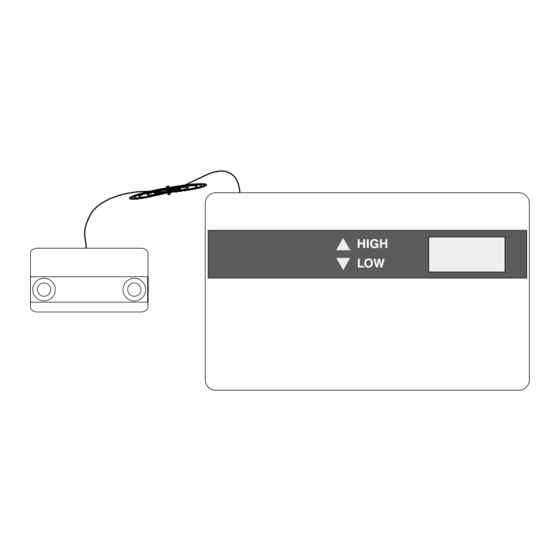
Using the temperature probe remotely:
Using the temperature probe locally:
Figure 2
Temperature Probe Housing
Figure 3
Temperature Probe PCB
MOUNTING
HOLE
Remove Wire Tie
TB1
V+
V-
NC
C
Temperature Probe PCB
Mounting Pins
Advertisement
Table of Contents

Subscribe to Our Youtube Channel
Related Manuals for IntelliSense Intellitemp T-1000

Summary of Contents for IntelliSense Intellitemp T-1000
- Page 1 IntelliTemp c T-1000 INSTALLATION INSTRUCTIONS IMPORTANT: HIGH MOUNTING PROCEDURE NOTE: Using the temperature probe remotely: Using the temperature probe locally: Figure 2 MOUNTING LOCATION Temperature Probe Housing Figure 1 T-1000 Top Housing Removed WIRE TEMPERATURE PROBE MOUNTING PINS KNOCKOUTS Figure 3 TEMP Temperature Probe PCB TRANSDUCER...
-
Page 2: Specifications
Cet appareil numérique de la Classe B respecte toutes les exigences du Règlement sur le matériel brouilleur du Canada. © 2001 IntelliSense ® • IntelliSense is a registered trademark of Honeywell, Inc. IntelliTemp is a trademark of Honeywell, Inc. • All other trademarks are the properties of their respective owners. • All rights reserved.
Need help?
Do you have a question about the Intellitemp T-1000 and is the answer not in the manual?
Questions and answers