Advertisement
Advertisement

Summary of Contents for Andivi TRC-d
- Page 1 ANDIVI TRC-D TECHNICAL MANUAL 08/14, fw. ver. V1.2, V1.3 www.andivi.com...
- Page 2 • Carefully read these instructions before starting the installation. • Room controller Andivi must be installed according to applicable standards. • Before any intervention, make sure the power is turned off.
-
Page 3: Table Of Contents
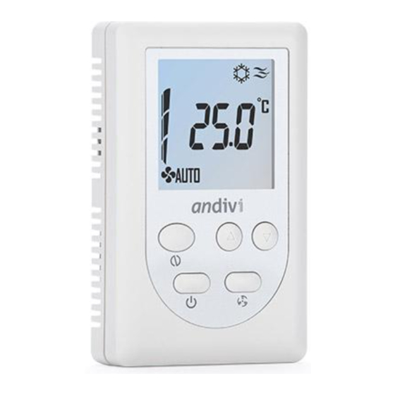
Andivi – TRC-D – Technical Manual INDEx FRONT VIEW (LEGEND OF SYMBOLS) INSTALLATION MOUNTING ON ELECTRIC BOX MOUNTING THE FRONT COVER WIRING EXAMPLE OPERATION ROOM CONTROLLER TYPES USER MODE OPERATION WORKING MODE COOLING MODE HEATING MODE “ON” FUNCTION ANTI-FREEZING PROTECTION... - Page 4 Intelligent room controller TRC-D TECHNICAL MANUAL Fig 1-1: Front view Item Description FIRE icon or FLAKE icon Fire icon for Heating action; Flake icon for Cooling action ON/ACTIVE icon Indicate room controller ON status SLEEP icon [not used] CLOCK icon...
-
Page 5: Installation
Andivi – TRC-D – Technical Manual INSTALLATION MOUNTING ON ELECTRIC BOX 1. Separate the back plate from the controller by loosening the cover screw. 2. Align the mounting holes on the screw holes of the electric box. Suitable is a 3-module electric box 3M, for example Gewiss GW24203, GW24207;... -
Page 6: Operation
Andivi – TRC-D – Technical Manual OPERATION ROOM CONTROLLER TYPES The type of room controller is selectable in the Engineer mode and over the Modbus communication. Item Description B - Type 4-Pipe Heating or Cooling (Manually Selectable) C - Type... -
Page 7: Working Mode
Andivi – TRC-D – Technical Manual WORKING MODE 1. For Cooling or Heating mode manually selectable type (B, E), working mode depends on the users’ setting. 2. For Cooling Heating mode automatical changeover type (C), working mode depends on the Room... -
Page 8: Heating Mode
Andivi – TRC-D – Technical Manual hEATING MODE Stage Differential Valve control for Heating mode Stage Valve Differential active Valve Valve active not active Current Set-point Temperature Valve not active Current Heating Set-point Temperature Heating FAN control for Heating mode... -
Page 9: Economy Mode
Andivi – TRC-D – Technical Manual Type Room controller OFF Room controller ON 2-Pipe system (E) Valve is always ON Valve is always ON 4-Pipe system (B or C) Heating valve is always ON Heating valve is always ON Valve control for Anti-Freezing Differential (°C) -
Page 10: Engineer Mode Operation
Andivi – TRC-D – Technical Manual ENGINEER MODE OPERATION It is highly recommended for this mode to be operated by trained engineers because it is related to system parameters that will affect the control results. To operate: 1. Press UP and DOWN buttons for over 5 seconds to enter Engineer mode. - Page 11 Andivi – TRC-D – Technical Manual ENGINEER MODE MENU ITEMS DESCRIPTION °C Type °F Type Item Mnemonic Description Step Default Range Default Range ESIC Protect (PROT) Cooling set-point 30.0 20.0~40.0 86.0 68.0~104.0 0.1°C/°F ESIH Protect (PROT) Heating set-point 15.0 00.0~25.0 59.0...
- Page 12 Andivi – TRC-D – Technical Manual OP-L Not used SPAn Not used rE-C Not used rE-H Not used HFAn Maximum fan speed Output control Bit Value: 0: output controlled with internal r. controller 1: output directly controlled via Modbus communication...
-
Page 13: Network Specifications
Andivi – TRC-D – Technical Manual NETWORK SPECIFICATIONS Transmission • Physical layer: RS485 (2 wires) • Baud rate: 19200 bps • Data format (RTU mode): 1 start bit, 8 data bits, no parity check, 2 stop bit Modbus • Address range: 1~247. - Page 14 Andivi – TRC-D – Technical Manual READ/WRITE COILS (FUNCTION CODE 01/05/15) Function Register Description Definition code address Status of room controller 0: Off / 1: On Status of Protect mode 0: Protect mode not active / (Active only when the local PROTECT detection is disabled. Please refer to 1: Protect mode active Modbus holding register address 6, and Engineer table parameter 03 - LOC.)
- Page 15 Andivi – TRC-D – Technical Manual READ DISCRETE INPUT (FUNCTION CODE 02) Function Register Description Definition code address Status of Protect mode (Effective only when the local PROTECT detection is enabled. Please 0: Protect mode not active / refer to Modbus holding register address 6, and Engineer table 1: Protect mode active parameter 03 - LOC.)
- Page 16 Andivi – TRC-D – Technical Manual READ/WRITE hOLDING REGISTER (FUNCTION CODE 03/06/16/23) Function Register Description Definition code address 03/06/16/23 0~500 (0~50.0°C) Heating/Cooling mode (*“Command write” only for 03/06*/16*/23* 0: Cool / 1: Heat Cooling or Heating mode selectable type) 0: Off / 1: Manual Stage I / 2: Manual Stage II /...
- Page 17 Andivi – TRC-D – Technical Manual 03/06/16/23 Maximum fan speed 0: Off / 1: Stage I / 2: Stage II / 3: Stage III Bit value: 0: Output controlled with internal r. controller 1: Output directly controlled via Modbus communication...
- Page 18 Andivi – TRC-D – Technical Manual READ INPUT REGISTER (FUNCTION CODE 04) Function Register Description Definition code address Current temperature 200~1000 (-20.0~100.0°C) 0: Off / 1: Stage I / Fan speed 2: Stage II / 3: Stage III Cooling controller...
-
Page 19: Warranty, Conditions
Before being able to claim under this Limited Warranty, the owner of the Some jurisdictions do not allow limitations on how long an implied Product must (a) notify Andivi of the intention to claim by sending and e-mail warranty lasts or exclusions/limitations on incidental or consequential to info@andivi.com<mailto:info@andivi.com>...
Need help?
Do you have a question about the TRC-d and is the answer not in the manual?
Questions and answers