
Related Manuals for Newcon Optik NVS 7-3XT

Summary of Contents for Newcon Optik NVS 7-3XT
- Page 1 Operation Manual NVS 7 Series NIGHT VISION BINOCULARS/GOGGLES NVS 7-3XT, NVS 7-3AG, NVS 7-3AGBW, NVS 7-3/4xXT, NVS 7-3/5xXT, NVS 7-3/8xXT NSN: 5855-20-000-8284 105 Sparks Ave., Toronto, ON, M2H 2S5, Canada...
- Page 3 IMPORTANT INFORMATION Read prior to activation. You have purchased a sophisticated electronic device. To operate it properly, please read this manual carefully. Ignoring the operation procedures described in this manual will void your warranty. NEVER disassemble the Unit. This device contains a source of high voltage, which may be hazardous to your health.
- Page 4 Precautions All NVS 7 series devices are sophisticated precise electro-optical instruments. It should be handled with due care: Each Unit contains fragile components. Avoid hard impacts, dust, moisture and abrupt changes of temperature. Do not touch the optical surfaces other than for cleaning with an appropriate lens cleaning kit.
-
Page 5: Table Of Contents
CONTENTS NVS 7 Series Models OVERVIEW .............. 3 DELIVERY SET ............5 Standard delivery set ............5 Optional accessories ............5 SPECIFICATIONS ............ 6 UNIT DESIGN ............8 OPERATION INSTRUCTIONS ....... 9 ... - Page 6 Defogging options ............17 TROUBLESHOOTING ........... 19 No green (or black and white) image visible ....19 Image is unclear ............. 19 Image flashes ..............19 Condensation accumulates on Unit ........ 19 Visibility decreased or disappeared ....... 19 ...
-
Page 7: Overview
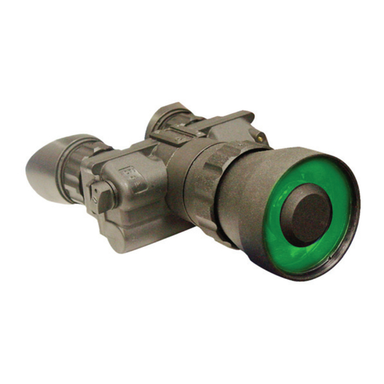
1. OVERVIEW Your NVS 7 series device (the “Unit”) is an optoelectronic goggle intended for observation of objects and orientation at night or under dark conditions. The Unit is equipped with an advanced Generation 3 (“Gen 3”) image intensifier tube (“IIT”), which amplifies low light, such as moonlight, starlight or man- made light and converts it into a clear visible image. - Page 8 NVS 7 Series Models Model Brief Description NVS 7-3XT Military specification night vision goggles with 1x magnification, Gen 3 IIT, helmet/head mountable, green image. NVS 7-3AG Military specification night vision goggles with 1x magnification, Gen 3 IIT, auto- gated power supply helmet/head mountable, green image.
-
Page 9: Delivery Set
Optional accessories 3x Afocal Lens Hard case Lens Cleaning Kit NVS H Mount (helmet mount) Demist Shield/Sacrificial Window NVS Coupler Exact Delivery Set is subject to specific contract terms. NVS 7-3XT, NVS 7-3AG, NVS 7-3AGBW NVS 7-3/4xXT, NVS 7-3/5xXT, NVS 7-3/8xXT... -
Page 10: Specifications
3. SPECIFICATIONS Model 3AGBW IIT Generation Gen 3 Photocathode Material Gallium Arsenide (GaAs) Image Colour Green Black & White Photocathode Diameter 17.5mm 1800 µA/lm Minimum Photocathode Sensitivity 190 mA/W 40,000 – 70,000 fL/fc Luminous Gain 10,000 – 20,000 fL/fc Auto-gating ... - Page 11 Battery Life Over 80 hours without IR; over 30 hours with IR Low Battery Indicator IR ON Indicator Waterproof MIL-STD-810G Maximum Current Consumption 25mA Voltage 2.80.8 V 1x: 150x120x55mm; 4x: 165x120x70mm Dimensions 5x: 230x136x82mm; 5x: 240x130x130mm 1x: 480g; 4x: 690g Weight 5x: 800g;...
-
Page 12: Unit Design
4. UNIT DESIGN FIGURE 1 AUTO/OFF/ON/IR switch Mounting socket Diopter adjustment ring Eyepieces Battery compartment cover Objective lens cap Objective lens Tightening knob Release button IR illuminator FIGURE 2... -
Page 13: Operation Instructions
5. OPERATION INSTRUCTIONS Installing battery Unpack the device. Unit is supplied with battery not installed. Prior to installing the battery, make sure the AUTO/OFF/ON/IR switch (1, Fig.1) is in the OFF position and the objective lens cap (6, Fig, 1) is on. Unscrew the battery compartment cover (5, Fig.1), and install 2 fresh AA batteries. -
Page 14: Switching The Unit Off
3). When this indicator is blinking this indicates low battery power. For uninterrupted operation keep fresh batteries ready and replace them on time. If this indicator is displayed as a solid red light, this indicates that the IR illuminator is activated. This warning is intended to prevent the user from unintentionally giving away their position. -
Page 15: Focusing The Unit
Focusing the Unit Turn on the Unit. Direct the device at an object placed within 8- 15 m from the viewer. While looking through the Unit at the object, first rotate the diopter adjustment ring on each eyepiece (3, Fig. 1). Once focus is nearly achieved, rotate the objective lens (7, Fig. -
Page 16: Auto Shut Off In Flip Up Position (Auto Switch Position)
3. To detach the current lens: hold the lens by its base and rotate it counter-clockwise. Once the lens has been removed, store it in a safe, clean space. 4. To attach desired lens: rotate it clockwise along the threading until snug—do not overtighten. The threads are very fine (to prevent humidity penetration) and can be damaged easily. -
Page 17: Auto Shut Off At Bright Light
Auto shut OFF at bright light Each unit has a built-in high light sensor located near the IR illuminator (10, Fig. 1). This sensor shuts the goggles off after approximately 40 seconds of exposure to light exceeding 40 lux. To reset the device after auto shut off, switch it off and then back on as described in Section 5. -
Page 18: Integrated Protection Circuits
the IIT in changing lighting conditions. Auto-gating turns off the photocathode voltage for brief periods of time, but the effect is not visible to the human eye. This serves not only to protect the IIT from exposure to bright lighting sources, but also to automatically provide the user with the optimal image regardless of prevailing light condition. - Page 19 This function is still active in the device equipped with an auto- gated IIT. The BSP reduces voltage to the photocathode rather than the microchannel plate. The BSP protects the image intensifier tube from damage and enhances its lifetime. This function works in bright light conditions that create input light with intensity higher than 0.1lux.
-
Page 20: Using Nvs H Mount (Helmet Mount)
Using NVS H mount (helmet mount) FIGURE 4 FIGURE 7 Locking screw Flip-up adjusting screws Flip-up button Mount binding screw The Unit can be equipped with an optional NVS H Mount which fits a variety of existing helmet models. The Unit is fixed to the mount via a locking screw (1, Fig. 4). -
Page 21: Defogging Options
point can be adjusted using the flip-up adjustment screws (3, Fig. 4). If you loosen them, you can rotate the flip-up mechanism to find the suitable starting point. Tighten the screws after completing the adjustment. You can raise the Unit for unobstructed view without taking the helmet off. - Page 22 Sacrificial Window – prevents fogging and moisture build up on the objective lens. The sacrificial window snaps on top of the objective lens and seals it from any water particles in the air. On the Figure 6 the NVS 7 unit is shown with installed sacrificial window.
-
Page 23: Troubleshooting
6. TROUBLESHOOTING No green (or black and white) image visible Check that the batteries are installed properly and are full charged. Wrongly installed and expended batteries are the most common problems leading users to believe their Unit is defective. Image is unclear Check if the lenses are foggy or dusty. -
Page 24: Warranty
Newcon Optik dealer. Newcon Optik will repair (or, at its option, replace with the same or comparable model), the product or part thereof, which, on inspection by Newcon, is found to be defective in materials or workmanship. -
Page 25: Customer Support
8. CUSTOMER SUPPORT Should you experience any difficulties with your Newcon Optik product, consult this manual first. If the problem remains, contact our customer support department at +1 (416) 663-6963 or toll free at 1-877-368-6666 (North America only). Our operating hours are 0900h to 1700h Eastern Standard Time, Monday through Friday. -
Page 26: Acceptance Certificate
9. ACCEPTANCE CERTIFICATE Image intensifier tube serial number: _____________________ Characteristic Minimum Measured Resolution, lp/mm Photocathode sensitivity, integral, 1800 A/lm (@2856°K) Light amplification fL/fc (@2x10- 40,000 6 fc) Date of production:__________________________________ Quality Inspector’s signature: ___________________________... - Page 27 NVS 7-3/4xXT NVS 7-3AG NVS 7-3/5xXT NVS 7-3AGBW NVS 7-3/8xXT Other: Unit serial number: _________________________________ This Unit complies with all technical specifications and has passed Newcon Optik’s inspection procedures. Date of production: _________________________________ Quality Inspector’s signature: __________________________ Quality Assurance Seal...
- Page 28 NEWCON OPTIK Printed in Canada...
Need help?
Do you have a question about the NVS 7-3XT and is the answer not in the manual?
Questions and answers