Toshiba 32D46 Service Manual
Color television
Hide thumbs
Also See for 32D46:
- Service manual supplement (21 pages) ,
- Specifications (2 pages) ,
- Owner's manual (76 pages)
Table of Contents
Advertisement
Quick Links
SERVICE MANUAL
COLOR TELEVISION
The above model is classified as a green product (*1), as indicated by the underlined serial number.
This Service Manual describes replacement parts for the green product. When repairing this green
product, use the part(s) described in this manual and lead-free solder (*2).
For (*1) and (*2), see the next page.
FILE NO. 050-200610GR
(MFR'S VERSION A)
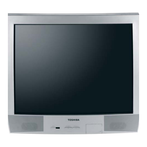
32D46
DOCUMENT CREATED IN JAPAN, April, 2006 GREEN
Advertisement
Table of Contents

Related Manuals for Toshiba 32D46


Summary of Contents for Toshiba 32D46
-
Page 1: Service Manual
(MFR’S VERSION A) SERVICE MANUAL COLOR TELEVISION 32D46 The above model is classified as a green product (*1), as indicated by the underlined serial number. This Service Manual describes replacement parts for the green product. When repairing this green product, use the part(s) described in this manual and lead-free solder (*2). -
Page 2: Green Product Procurement
Hazardous Substances. From July 1, 2006, the RoHS Directive will prohibit any marketing of new products containing the restricted substances. Increasing attention is given to issues related to the global environmental. Toshiba Corporation recognizes environmental protection as a key management tasks, and is doing its utmost to enhance and improve the quality and scope of its environmental activities. -
Page 3: Servicing Notices On Checking
SERVICING NOTICES ON CHECKING 1. KEEP THE NOTICES 6. AVOID AN X-RAY As for the places which need special attentions, Safety is secured against an X-ray by consider- they are indicated with the labels or seals on the ing about the cathode-ray tube and the high cabinet, chassis and parts. -
Page 4: Table Of Contents
TABLE OF CONTENTS GREEN PRODUCT PROCUREMENT ..................A1-1 LEAD-FREE SOLDER ........................ A1-1 SERVICING NOTICES ON CHECKING ..................A1-2 HOW TO ORDER PARTS ......................A1-2 IMPORTANT ..........................A1-2 TABLE OF CONTENTS ......................A2-1 GENERAL SPECIFICATIONS ....................A3-1~A3-6 DISASSEMBLY INSTRUCTIONS 1. REMOVAL OF ANODE CAP ....................B1-1 2. -
Page 5: General Specifications
GENERAL SPECIFICATIONS CRT Size / Visual Size 32 inch / 800.1mmV System CRT Type Normal Magnetic Field BV/BH +0.45G/0.18G Color System NTSC Speaker 2 Speaker Position Front Size 1.8 x 3.9 Inch Impedance Sound Output 2.5+2.5 W 10%(Typical) NTSC3.58+4.43 /PAL60Hz Tuning Broadcasting System Analog... - Page 6 GENERAL SPECIFICATIONS On Screen Menu Display Menu Type Icon Picture Mode(Picture preference) Contrast Brightness Color Tint Sharpness Color Temperature Reset Sound Bass Treble Balance BBE On/Off Stable Sound On/Off Audio Language Digital Output(PCM/Dolby Digital) Surround On/Off Reset Set Up Language Clock Set TV/Cable Auto CH Memory...
- Page 7 Timer Back-up (at Power Off Mode) more than G-10 Remote Unit RC-KK Control Glow in Dark Remocon Back Light Remocon Remocon Format Toshiba Format Toshiba Custom Code TV:40-BFh Power Source Voltage(D.C) UM size x pcs UM-4 x 2 pcs Total Keys...
- Page 8 GENERAL SPECIFICATIONS G-11 Features Auto Degauss Auto Shut Off Canal+ Cable(CATV) Anti-theft Rental Memory(Last CH) Memory(Last Volume) V-Chip(Analog & Digital) Type USA,Orion Type Auto Search CH Allocation Just Clock Function CH Label VM Circuit Full OSD Premiere Comb Filter Lines Auto CH Memory Hotel Lock Closed Caption(Analog &...
- Page 9 GENERAL SPECIFICATIONS G-12 Accessories Owner's Manual Language English /Spanish W/ Warranty Remote Control Unit Rod Antenna Poles Terminal Loop Antenna Terminal U/V Mixer DC Car Cord (Center+) Guarantee Card Warning Sheet Circuit Diagram Antenna Change Plug Service Station List Important Safety Instruction Dew/AHC Caution Sheet AC Plug Adapter Quick Set-up Sheet...
- Page 10 Height (cm) 40 (ORION SPEC:25) Container Stuffing Sets/40' container G-17 Cabinet Material Cabinet Cabinet Front PS 94V0 DECABROM Cabinet Rear PS 94V0 DECABROM Non-Halogen Demand Eyelet Demand G-18 Environment Environmental standard requirement (by buyer) Green procurement of Toshiba Pb-free Phase3(Pha A3-6...
-
Page 11: Disassembly Instructions
DISASSEMBLY INSTRUCTIONS 3. After one side is removed, pull in the opposite direction to 1. REMOVAL OF ANODE CAP remove the other. Read the following NOTED items before starting work. NOTE After turning the power off there might still be a potential Take care not to damage the Rubber Cap. -
Page 12: Removal And Installation Of Flat Package Ic
DISASSEMBLY INSTRUCTIONS When IC starts moving back and forth easily after REMOVAL AND INSTALLATION OF desoldering completely, pickup the corner of the IC using a FLAT PACKAGE IC tweezers and remove the IC by moving with the IC desoldering machine. (Refer to Fig. 2-3.) REMOVAL NOTE Put the Masking Tape (cotton tape) around the Flat... - Page 13 DISASSEMBLY INSTRUCTIONS INSTALLATION When bridge-soldering between terminals and/or the soldering amount are not enough, resolder using a Thin-tip Take care of the polarity of new IC and then install the new Soldering Iron. (Refer to Fig. 2-8.) IC fitting on the printed circuit pattern. Then solder each lead on the diagonal positions of IC temporarily.
-
Page 14: Service Mode List
SERVICE MODE LIST This unit is provided with the following SERVICE MODES so you can repair, examine and adjust easily. To enter the Service Mode, press both set key and remote control key for more than 2 seconds. Set Key Remocon Key Operations Releasing of V-CHIP PASSWORD. - Page 15 WHEN REPLACING EEPROM (MEMORY) IC If a service repair is undertaken where it has been required to change the MEMORY IC, the following steps should be taken to ensure correct data settings while making reference to TABLE 1. +0 +1 +2 +3 +4 +5 +7 +8...
-
Page 16: Re-Write For Digital Soft Firmware
RE-WRITE FOR DIGITAL SOFT FIRMWARE JG198 JG199 Flash UP-Date Soft JG176 USA SD DTV ROM Serial Communication Disc DISC Change JIG Ref. No. Part No. Parts Name Remarks Serial Communication JG198 APJG198000 Connect the set to personal computer Change JIG Up-Date of the Firmware JG199 APJG199000... -
Page 17: Electrical Adjustments
ELECTRICAL ADJUSTMENTS 1. ADJUSTMENT PROCEDURE FUNCTION FUNCTION OSD H Read and perform these adjustments when repairing the CONT.CENT OSD C CONT.MAX circuits or replacing electrical parts or PCB assemblies. CUT OFF CONT.MIN H.POSI COL.CENT CAUTION H BLK L COL.MAX H BLK R COL.MIN Use an isolation transformer when performing any •... - Page 18 ELECTRICAL ADJUSTMENTS 2-5: BRIGHT CENT Receive the monoscope pattern. (RF Input) Set the screen mode to FULL. Using the remote control, set the brightness and contrast to normal position. Activate the adjustment mode display of Fig. 1-1 and ìAî press the channel button (17) on the remote control to select "BRI CENT".
- Page 19 ELECTRICAL ADJUSTMENTS 2-10: HORIZONTAL SIZE 2-14: TRAPEZIUM Receive the monoscope pattern. Receive the crosshatch signal from the Pattern Generator. Using the remote control, set the brightness and Using the remote control, set the brightness and contrast contrast to normal position. to normal position.
- Page 20 ELECTRICAL ADJUSTMENTS 2-17: OSD POSITION Receive the monoscope pattern from the Pattern Generator. Using the remote control, set the brightness and contrast to normal position. Activate the adjustment mode display of Fig. 1-1 and press the channel button (00) on the remote control to select "OSD H".
-
Page 21: Purity And Convergence
ELECTRICAL ADJUSTMENTS 3. PURITY AND CONVERGENCE 3-3: STATIC CONVERGENCE ADJUSTMENTS NOTE Adjust after performing adjustments in section 3-2. NOTE Receive the crosshatch pattern from the color bar Turn the unit on and let it warm up for at least 30 generator. - Page 22 ELECTRICAL ADJUSTMENTS 4. ELECTRICAL ADJUSTMENT PARTS LOCATION GUIDE (WIRING CONNECTION) CRT PCB TP024 CD804 CP804 R805 TP022 J801 TP023 R803 CP806 R807 CP802B CP801B CP803 CD802 CP801A J702 CP101 J708 J704 J701 CP401 TP003 VR401 TP004 VR502 CP1001 SPEAKER CP802A DEGAUSS COIL S501 CD501...
-
Page 23: Micon/Chroma
MICON/CHROMA BLOCK DIAGRAM CHROMA IC IC601 LA76327M-A-MPB-E 35 XTAL 3.58 X601 FB401 J801 Q802, Q806 3.579545MHz B OUT BLUE OUT FRONT -VIDEO VIDEO IN2 Q803, Q805 J753 G OUT GREEN OUT V801 Q801, Q804 30 Y IN V-OUT IC RED OUT R OUT YUV_IN IC401 LA7847-E... -
Page 24: Sd Digital Module
SD DIGITAL MODULE BLOCK DIAGRAM X2401 24.567MHz 16Mbit MOR FLASH IC2408 SST39VF1681-70-4C-EKE 256Mbit RESET DDRSAM +3.3V IC2404 HY5DU561622 DTP-D43 SD_DTV ASIC I2C1_CLK IC2401 I2C1_DATA ZR39640BGCG-B1 F/E_RESET TS_DATA TS_CLK TS_FRAME +2.6V TS_DVALID 8VSB/QAM/BTSC DEMOD. IC2402 ADATA CAS-220/CS BCLK +3.3V 94 93 AUDIO DAC IC2501 CS4345-CZZ... -
Page 25: Printed Circuit Boards
PRINTED CIRCUIT BOARDS TV MT/CRT (INSERTED PARTS) SOLDER SIDE C434 CP801A D411 D404 C415 J702 J701 CP101 B402 C427_1 J703 R408 J704 J708 W859 D405 W183 W049 L403 R411 B401 CME077A R441 D409 W177 Q003 R430 C715 HS002 C442 HS001 C425 FB401 IC005... - Page 26 PRINTED CIRCUIT BOARDS TV MT/CRT (CHIP MOUNTED PARTS) SOLDER SIDE Q105 R127 R125 R176 CCE070A R139 R137 Q102 R115 R150 Q107 R136 R624 R138 Q101 R104 R102 R107 R108 R110 R109 R128 R654 R169 R155 R168 R126 IC102 R638 R810 Q510 Q605 Q601...
-
Page 27: Digital/Front Jack
PRINTED CIRCUIT BOARDS DIGITAL (BOTTOM SIDE) DIGITAL (TOP SIDE) CEE139B CEE139B C2468 C2489 C2487 X2401 C2410 C2452 C2453 NR2408 C2490 C2402 C2488 C2411 B2402 C2403 C2412 C2406 R2464 R2457 C2405 R2456 C2493 R2465 C2492 R2494 C2425 C2444 C2424 C2515 C2420 C2430 R2509 C2443... - Page 28 MICON SCHEMATIC DIAGRAM (TV MT PCB) CP102 A2001WV2-7P W842 EEP_SCL SCL_EEP W860 EEP_SDA SDA_EEP W843 IIC_OFF IIC_OFF C101 SDA1 SDA2 0.01 B SCL1 SCL2 C139 FROM/TO AV SW/SOUND AMP/TONE CTL C104 SDA1 D112 SCL1 EEP ROM IC 128K IC S_IN MTZJ5.6B-EIC IC199 AT24C128N-10SU-1.8...
- Page 29 (TV MT PCB) CHROMA/IF SCHEMATIC DIAGRAM TU P 5V_SW FROM POWER Q611 S817X KTC3209_Y R631 P.CON+5V_SW Q609 1.8 1/4W KTC3209_Y UN_REG.12V P.CON+5V_SW C638 Q608 KTC3209_Y R651 R650 R657 R658 UN_REG.12V R625 R632 R623 FROM/TO AV SW/SOUND AMP/TONE CTL 1/4W 100 1/4W R647 R659 Y_IN...
- Page 30 DEFLECTION SCHEMATIC DIAGRAM (TV MT PCB) FROM/TO DY V.DRIVE IC IC401 LA7847-E V801 M80LNK085X90Y1J Pump up CP401 B06B-DVS-L_(LF) L402_2 S817Y 25.9 25.3 15.7 R423 ELH5L7120 R407 100K 1/4W R439 5.6K C425 TO CRT/SVM 0.001 CD803 (CP803) D402 CH823004 1N4002-PAN R414 R417 R459 R444...
- Page 31 POWER SCHEMATIC DIAGRAM (TV MT PCB) CP509 D516 RELAY DRIVE R515 003P-2100 Q504 10.9 1SS133 KTC3198 10K 1/4W RY501 G5PA-1-SA(WEC) C516 0.001 B TO AV SW/SOUND AMP/TONE CTL D505 W836 SOUND+B 7A 250V 21DQ09N D538 P.CON+9V DEGAUSS COIL R501 F502 L503 21DQ09N-FC4 CP502...
- Page 32 TUNER SCHEMATIC DIAGRAM (TV MT PCB) DIGITAL/ANALOG TUNER W/NTSC_MPX TU001 TO CHROMA/IF ENG36A49KF 31.45 3.36 3.36 3.36 1.69 2.37 4.96 4.96 W844 A_TUNER_CVBS C004 0.1 B C045 L004 220P C001 0.1 B 22uH 0305 C002 L003 6.3V 100uH L001 0305 C007 C024 0.01 B 22uH...
- Page 33 AV SW/SOUND AMP/TONE CTL SCHEMATIC DIAGRAM (TV MT PCB) R1014 YUV_IN(REAR) R1015 J704 MSP-213V1-652_NI_LF V_IN SOUND AMP IC IC1001 AN17822A U_IN FROM/TO CHROMA/IF Y_IN P.CON+5V VIDEO_IN1 AV2 AUDIO IN/COX OUT VIDEO_IN2 J708 S_VIDEO_IN[Y] MSP-213V2-732_NI_LF S_VIDEO_IN[C] C1003 AT+5V C727 R734 AUDIO_YUV[R] C1001 C724 R728...
- Page 34 CRT / SVM SCHEMATIC DIAGRAM CRT / SVM SCHEMATIC DIAGRAM (CRT PCB) L801 150uH 0607 R802 FROM DEFLECTION 2.7K 1/4W CP801B B2013H02-5P R803 RED OUT RED OUT FROM DEFLECTION 180V Q804 Q801 100.6 15K 2W C802 R812 KTC4217 KTC3199_Y CP806 123.0 005P-2100 0.001...
- Page 35 COMB/FILTER SCHEMATIC DIAGRAM (TV MT PCB) FROM TUNER D_Y_OUT D_C_OUT FROM/TO MICON L1511 DIGITAL_H 15uH 0305 BUFFER Q1508 2SC3052 C1535 L1505 15uH 0305 R1502 3.3K R1512 BUFFER Q1503 C1513 2SC3052 0.1 B W875 FROM/TO CHROMA/IF COMB FILTER IC IC1501 LA76605M-TLM-E COMB_Y C1529 COUT...
- Page 36 ASIC SCHEMATIC DIAGRAM (DIGITAL PCB) ASIC/CLEAR CABLE ASIC IC TO FLASH IC2401 ZR39640BGCG-B1 (1/8 VDD&GND) ATSC/CLEAR CABLE ASIC IC IC2401 ZR39640BGCG-B1 (3/8 I/F) C2412 10 C FOR IR RECIEVER C2413 0.1 B IVDD JG2401 C2414 0.1 B IVDD JG2409 C2415 0.1 B JG2410 IVDD...
- Page 37 SDRAM SCHEMATIC DIAGRAM (DIGITAL PCB) IC2401 ZR39640BGCG-B1 (4/8 DDR SDRAM) DDRDQ3 SDATA0 R2432 DDRA2 DDRDQ4 SADR2 SDATA1 DDRA3 R2433 DDRDQ1 SADR3 SDATA2 DDRDQ2 NR2410 SDATA3 4D02WGJ0220TCE DDRA5 DDRDQ6 SADR5 SDATA4 DDRCKE SCKE 256Mbit DDR SDRAM IC DDRA7 DDRDQ0 SADR7 SDATA5 IC2404 HY5DU561622DTP-D43 DDRA9...
- Page 38 FLASH SCHEMATIC DIAGRAM (DIGITAL PCB) ATSC/CLEAR CABLE ASIC IC IC2401 ZR39640BGCG-B1 (5/8 FLASH MEMORY) GDAT15 JG2411 GDAT14 JG2412 GDAT13 GDAT13 GDAT12 GDAT12 16Mbit(x8) NOR FLASH Firm wrote IC GDAT11 GDAT11 IC2408 SST39VF1681-70-4C-EKE GDAT10 GDAT10 GDAT8 GDAT9 GDAT9 GDAT9 GADR15 GDAT8 GDAT8 GADR14 GDAT7...
- Page 39 FRONT END SCHEMATIC DIAGRAM (DIGITAL PCB) C2401 R2471 0.1 B FROM AV OUT C2552 R2442 IF_OUT1_P 0.01 B C2555 R2443 IF_OUT2_N 0.01 B B2408 C2505 FCM1608KF-151T06 C2503 C2479 56P CH 100P CH C2504 L2402 C2508 0.1 B 0.22uH C2513 R2508 C2509 0.1 B C2514...
- Page 40 AV OUT SCHEMATIC DIAGRAM (DIGITAL PCB) POWER_GND B3404 HCB3216KF-601T20 B3402 +2.6V HCB3216KF-601T20 B3405 ASIC+1.8V B3403 HCB3216KF-601T20 +3.3V FCM1608KF-151T06 B2405 FCM1608KF-151T06 CLOSE TO CP2403 FROM/TO FRONT END ATSC/CLEAR CABLE ASIC IC2401 ZR39640BGCG-B1 (7/8 COMPONENT VIDEO) F/E+1.8V IF_OUT1_P IF_OUT2_N AVID_PR IF_AGC ADATA_DEMOD TU_CLK L2404 AVID_Y...
- Page 41 AV JACK SCHEMATIC DIAGRAM (FRONT JACK PCB) FROM AV SW/SOUND AMP/TONE CTL CD701 CH242001 W805 VIDEO VIDEO AUDIO_R J753 AV1-06AD-3 AUDIO_L W801 W804 AUDIO_L J752 AV1-06AD-4 W802 W803 AUDIO_R J751 AV1-06ADS-2 PCB280 NOTE:THE DC VOLTAGE AT EACH PART WAS MEASURED NOTE:THIS SCHEMATIC DIAGRAM IS THE LATEST AT THE TIME CED038 WITH THE DIGITAL TESTER WHEN THE COLOR BROADCAST...
-
Page 42: Micon
WAVEFORMS DEFLECTION POWER ON 20µs 10µs 200mV 10.0V AV/SOUND 20µs 20µs 20µs 200mV CHROMA/IF DEFLECTION 10µs 10ms 20µs 200mV 0.5V MICON 2µs 50µs 50µs 20µs 0.1ms 20µs NOTE: The following waveforms were measured at the point of the corresponding balloon number in the schematic diagram. -
Page 43: Crt/Svm
WAVEFORMS DEFLECTION 50µs 200V AV/SOUND 20µs 200mV CRT/SVM 20µs 20µs 20µs NOTE: The following waveforms were measured at the point of the corresponding balloon number in the schematic diagram. -
Page 44: Mechanical Exploded Views
MECHANICAL EXPLODED VIEW 102B 102B 102B 102A PCB110 (CRT PCB ASS'Y) PCBDH0 (DIGITAL PCB ASS'Y) 101I PCB070 (MAIN PCB ASS'Y) 101F 101G 101H PCB260 101H 101F (FRONT JACK PCB ASS'Y) 101G 101D 101I 101H 101B 101H 101E 101C 101A... - Page 45 MECHANICAL EXPLODED VIEW (PACKING DIAGRAM) 124, 125, 126, TM101...
-
Page 46: Mechanical Replacement Parts List
MECHANICAL REPLACEMENT PARTS LIST Location No. TSB P/N Reference No. Description 72783580 7A7010190A FRONT CABI ASS'Y 101A 72783560 701WPJ1412 CABINET,FRONT 101B 72798490 711WPA0191 PLATE,FRONT 101C 72798497 712WPBA085 DOOR 101D 72798519 713WPA0288 GLASS,LED 101E 72783551 7230008094 AV,LABEL 101F 72798590 735WPA0769 STOPPER,BUTTON 101G 72798603 735WPBA985... -
Page 47: Electrical Replacement Parts List
ELECTRICAL REPLACEMENT PARTS LIST Location No. TSB P/N Reference No. Description RESISTORS ! R002 72794621 R3X28B010J R,METAL OXIDE OHM 3W ! R004 72794621 R3X28B010J R,METAL OXIDE OHM 3W ! R007 72794621 R3X28B010J R,METAL OXIDE OHM 3W ! R408 72794614 R65582010J R,FUSE OHM 1/2W ! R410... - Page 48 ELECTRICAL REPLACEMENT PARTS LIST Location No. TSB P/N Reference No. Description DIODES D109 72795529 0021721150 SLR-342VCT32 D110 72795627 D2WXSB1400 DIODE,SCHOTTKY SB140-EIC D111 72795627 D2WXSB1400 DIODE,SCHOTTKY SB140-EIC D112 72783214 D9WU05R62B DIODE,ZENER MTZJ5.6B-EIC D113 72783214 D9WU05R62B DIODE,ZENER MTZJ5.6B-EIC D114 72783214 D9WU05R62B DIODE,ZENER MTZJ5.6B-EIC D401 72783209...
- Page 49 ELECTRICAL REPLACEMENT PARTS LIST Location No. TSB P/N Reference No. Description IC102 72795101 I9UF032290 PST3229NR IC199 75002703 S3W502HE01 MEMORY DATA AT24C128N-10SU-1.8 IC301 72783378 I5AFF11730 NJW1173V(TE1) ! IC401 72783379 I03SD78470 LA7847-E ! IC504 72794512 000220002W PHOTO COUPLER PS2561AL1-1-V(W) IC601 72783380 I03FC6327A LA76327M-A-MPB-E IC701 72783381...
- Page 50 ELECTRICAL REPLACEMENT PARTS LIST Location No. TSB P/N Reference No. Description COILS &TRANSFORMERS L301 72794526 02167F220J COIL L402 72796596 022100031A COIL,LINEARITY ELH5L7120N ! L403 72794529 02DK000058 COIL,CHOKE 02DK000058 ! L501 72796639 029X000098 COIL,LINE FILTER SS28H-20075 L502 72796513 02167E220K COIL R7 22 ! L503 72796624 028R320005...
- Page 51 ELECTRICAL REPLACEMENT PARTS LIST Location No. TSB P/N Reference No. Description MISCELLANEOUS B2421 72783357 024HC51513 CORE,BEADS FCM1608KF-151T06 B2423 72783356 024HC51023 CORE,BEADS FCM1608KF-102T02 B2501 72783356 024HC51023 CORE,BEADS FCM1608KF-102T02 B3402 72783358 024HC16014 CORE,BEADS HCB3216KF-601T20 B3403 72783357 024HC51513 CORE,BEADS FCM1608KF-151T06 B3404 72783358 024HC16014 CORE,BEADS HCB3216KF-601T20 B3405...
- Page 52 TOSHIBA CORPORATION 1-1, SHIBAURA 1-CHOME, MINATO-KU, TOKYO 105-8001, JAPAN...
Need help?
Do you have a question about the 32D46 and is the answer not in the manual?
Questions and answers