Table of Contents
Advertisement
Advertisement
Table of Contents

Subscribe to Our Youtube Channel
Summary of Contents for Vermona Filter lancet
-
Page 2: Introduction
In addition, such manipulation should be intui- tive. A good filter box therefore demands lots of knobs, switches and connections. FILTER Lancet was created to be a highly flexible and easy to use filter box with multiple possibilities to be controlled. As you can expect from VERMONA, this unit uses finest analogue technology. - Page 3 Owner's Manual VERMONA Filter Lancet 11. Only use attachments/accessories specified by the manufacturer. 12. Use only with the cart, stand, tripod, bracket, or table specified by the manufacturer, or sold with the apparatus. When a cart is used, use caution when moving the cart/apparatus combination to avoid injury from tip-over.
-
Page 4: Table Of Contents
Owner's Manual VERMONA Filter Lancet Table of Contents 1 Introduction ........................2 Important Safety Instructions ................3 Table of Contents ...................... 4 Getting Started ......................4.1. Connections and Powering ..............5 Components and Controls ..................5.1. Input Section (IN) ................ -
Page 5: Getting Started
Connect the OUTPUT jack of FILTER Lancet to an appropriate audio input of a mixing console, an audio-interface or an amplifier. Start FILTER Lancet by switching on OVERKILL on the unit’s rear. The corresponding green LED will be lit. Congratulations, FILTER Lancet has been started. -
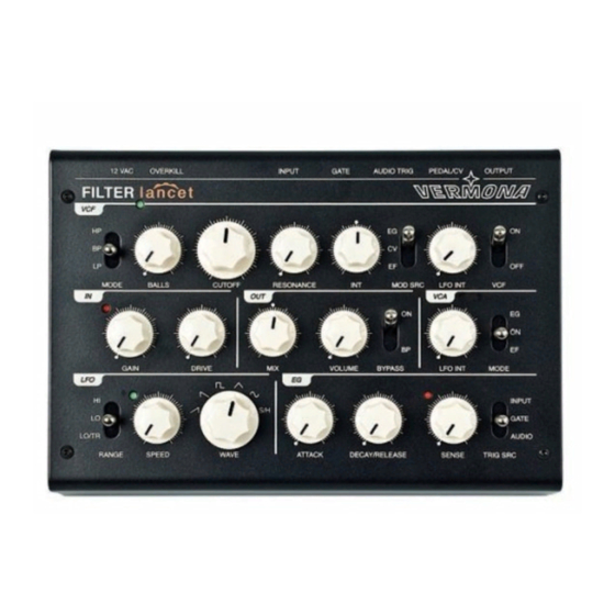
Page 6: Components And Controls
Components and Controls Filter Lancet is a filter box. Beside its central sound shaping element, a multimode filter, it offers further functions such as overdrive, VCA, LFO and an envelope-generator. This section will take a closer look to the different sections of FILTER Lancet and their correspondent control elements. -
Page 7: Output Section (Out)
MIX turned fully counterclockwise, the input signal passes through the input section with possible distortion and straight to the output. With MIX turned fully clockwise, only the signal processed with VCF and VCA will be audible. VOLUME This control sets the output level of FILTER Lancet. - 7 -... -
Page 8: Filter (Vcf)
Owner's Manual VERMONA Filter Lancet BYPASS Setting this switch to BP to disable all sections of FILTER Lancet. The input signal is passed directly to the output after the GAIN stage. With the switch set to ON, all sections are active. - Page 9 Owner's Manual VERMONA Filter Lancet The filter section offers the following control elements: Picture 3: Filter (VCF) MODE MODE selects the filter type. LP = Low pass Low pass filter with a slope of 24dB per octave BP = Band pass Band pass filter with a slope of 12dB per octave HP = High pass High pass filter with a slope of 24dB per octave...
- Page 10 filter. Here, specific frequencies are always suppressed. CUTOFF has a larger control knob intentionally. This is the most impor- tant function of FILTER Lancet and turning this knob should be fun! RESONANCE Resonance is a feedback circuit within the filter that emphasizes the CUTOFF frequency.
- Page 11 Combing an envelope-follower with rhythmic audio-sig- nals such as drum loops is quite useful. Another useful application is using a guitar with the FILTER Lancet set to band pass filtering with audible resonance. An envelope- follower will create a sound that resembles of the typical Autowah-effect.
-
Page 12: Amplifier (Vca)
Owner's Manual VERMONA Filter Lancet Amplifier (VCA) A voltage-controlled-amplifier (VCA) controls FILTER Lancet’s output. It offers the following control elements: Picture 4: Amplifier (VCA) LFO INT This control sets the LFO's modulation intensity towards the output volume. The result is a tremolo-effect. -
Page 13: Modulation
Owner's Manual VERMONA Filter Lancet Modulation Modulation-Generator (LFO) The LFO (Low Frequency Oscillator) is an oscillator specialized on slow fre- quencies that are used to create cyclic repeating modulations. Its frequency is variable, ranging from 0.05Hz to 300Hz, being divided in two switchable ranges. -
Page 14: Envelope-Generator (Eg)
Owner's Manual VERMONA Filter Lancet Envelope-Generator (EG) FILTER Lancet’s envelope generator (EG) generates a variety of envelope shapes depending on the trigger source used. It will work as an Attack/ Decay envelope when using triggers from the audio input or the AUDIO TRIG-input. -
Page 15: Envelope Follower (Ef)
Picture 7: Connecting volume pedals Analogue control voltages ranging from 0-5 volts can be connected to the PEDAL/CV input. This allows FILTER Lancet to be controlled from external CV-sources such as step-sequencers, key-CV of analogue syn- thesizers, LFOs with special functions as well as Theremin antennas. -
Page 16: Further Control Elements
This audio input can trigger the envelope-generator. PEDAL/CV Allows connecting a CV-source or a pedal to control the CUTOFF- frequency. OUTPUT Carries the output signal of FILTER Lancet to be connected to a mixing console, an audio-interface or an amplifier. - 16 -... -
Page 17: Technical Specifications
Owner's Manual VERMONA Filter Lancet Technical Specifications Input max. Input Level -32dBu Impedance 1MΩ Output max. Output Level 20dBu Impedance 600Ω Audio Trigger max. Input Level -32dBu Impedance 1MΩ GATE min. trigger voltage CV Input voltage +/-5V Signal-to-Noise Ratio Direct >80dB... - Page 18 Owner's Manual VERMONA Filter Lancet Switch Range: Lo/Trigger, Lo, Hi Envelope-Generator Attack 1ms..10s Decay/Release 1ms..15s Controller Attack, Decay/Release, Trigger Sense Switch Trigger Source: Input, GATE, Audiotrigger Input-/Output section Controller Gain, Drive, Mix, Volume Switch Bypass Product Properties Jacks Input, GATE, Audio Trig, Pedal/CV,...
-
Page 19: Declaration Of Conformity
Owner's Manual VERMONA Filter Lancet Declaration of Conformity We declare under our sole responsibility that this product is in conformity with the following standards or standardization documents in attention of operation conditions and installation arrangements acc. to operating manual: EN61000-3-2, EN 61000-3-3, EN 55013, EN 55020, EN 60065 according to the provisions of the regulations 2004/108/EG and 2006/95/EG.
Need help?
Do you have a question about the Filter lancet and is the answer not in the manual?
Questions and answers