Table of Contents
Advertisement
Advertisement
Table of Contents

Summary of Contents for High End Systems SolaSpot Pro 1500
- Page 1 Professional Moving Head User Manual Version 1.0.0...
-
Page 2: Table Of Contents
Table of Contents Welcome Contacting High End Systems ® Patents Warranty Information Important Safety Information Fixture Overview Features Safety Considerations General Guidelines Installation Instructions Dimensional Drawings Mounting Orientations Linking Fixtures DMX Start Address Fixture Control Board Control Board Functions Preset Programming and Playback... -
Page 3: Welcome
Trademarks used in this text: High End Systems, Wholehog, and Lithopatterns are registered trademarks: and intellaspot, Internal Effects, the High End Systems globe logo, and the Hog logo are trademarks of Barco Lighting Systems, High End Systems, Inc. is a registered trademark. -
Page 4: Contacting High End Systems
Contacting High End Systems ® Sales Department High End Systems, Inc. 2105 Gracy Farms Lane Austin, TX 78758 USA voice:512.836.2242 fax:512.837.5290 Toll Free: 800.890.8989 Customer Service High End Systems, Inc. 2105 Gracy Farms Lane Austin, TX 78758 USA voice:800.890.8989 fax: 512.834.9195 toll free: 800.890.8989... -
Page 7: Patents
Patents This High End Systems product is protected by patents and pending patent applications. Patents owned or licensed by High End Systems include: US 4,392,187; US 4,602,321; US 4,688,161; US 4,701,833; US 4,709,311; US 4,779,176; US 4,800,474; US 4,962,687; US 4,972,306; US 4,980,806; US 5,010,459; US 5,031,078; US 5,073,847; US 5,078,039; US 5,186,536; US 5,209,560;... -
Page 9: Warranty Information
The manufacturer will make the final determination as to whether or not the unit is covered by warranty. A fixture must be returned in its original packaging. Any other parts returned to High End Systems must be packaged in a suitable manner to ensure the protection of such product unit or parts, and such package shall be clearly and prominently marked to indicate that the package contains returned Product units or parts and with an RMA number. -
Page 10: Important Safety Information
Important Safety Information Instructions pertaining to continued protection against fire, electric shock, and injury to persons are found throughout this manual. Please read all instructions prior to assembling, mounting, and operating this equipment. The following international caution and warning symbols appear in margins throughout this manual to highlight messages. -
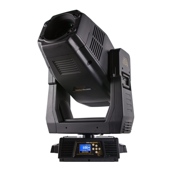
Page 11: Fixture Overview
Fixture Overview 1: Lens 2: Handle 3: Microphone 4: Display 5: Left-button 6: Down-button 7: ENTER-button 8: Right-button 9: Mode/Esc-button 10: Up-button 11: 5-Pin DMX out 12: 5-Pin DMX in 13: 3-Pin DMX in 14: 3-Pin DMX out 15: Power supply 16: Fuse... - Page 12 This page intentionally left blank to ensure new chapters start on right (odd number) pages.
-
Page 13: Features
Features •DMX Channels mode: 48 channels •Stand alone operation with Master/Slave function, sound activated via built in microphone. •Pan and tilt movement: 8 and 16 bit resolution For smooth and precise motion Movement: Pan: 540°/630°optional, Tilt: 265° Speed of pan/tilt movement adjustable Scan position memory, auto reposition after unexpected movement •Colors: Basic color wheel with 6 dichroic mirrors, plus white, two direction rainbow effect. -
Page 14: Safety Considerations
Safety Considerations This device has left the factory in perfect condition. In order to maintain this condition and to ensure a safe operation, it is absolutely necessary for the user to follow the safety instructions and warning notes written in this user manual. Important: Damages caused by the disregard of this user manual are not subject to warranty. -
Page 15: General Guidelines
General Guidelines This device is a lighting effect for professional use on stages, theaters, or other professional installations, etc., the device was designed for indoor use only. This fixture is only allowed to be operated with the max alternating current which stated in the technical specifications printed on the fixture. -
Page 16: Installation Instructions
Installation Instructions The installation must always be secured with a secondary safety attachment, e.g. an appropriate safety cable. Never stand directly below the device when mounting, removing or servicing the fixture. The operator has to make sure the safety and technical installations are approved by an expert before tak- ing using this fixture in the field for the first time. -
Page 17: Dimensional Drawings
Dimensional Drawings Dims listed in (MM) -
Page 18: Mounting Orientations
Mounting Orientations Be sure this fixture is kept at least 0.5m (1.6ft) away from any flammable materials (decoration etc.). Always use and install the sup- plied safety cable as a safety measure to prevent accidental damage and/or injury in the event the clamp is improperly installed or fails. -
Page 19: Linking Fixtures
Linking Fixtures The SolaSpot Pro 1500 fixture operates on standard DMX512 link controlled by a DMX console. The number of fixtures on a link will be determined by the combined number of channels required by all the fixtures. A SolaSpot Pro CMY fixture requires a 48 channel footprint on a standard DMX512 link. - Page 20 Connecting to the Link To link one or more fixtures to a DMX controller: Connect the male XLR connector of a DMX Data cable to the controller’s DMX Data Out connector. Connect the Data cable’s female XLR connector to the Data In connector of the first (or next) fixture on the DMX link.
-
Page 21: Dmx Start Address
DMX Start Address All fixtures should be given a unique DMX starting address when using a DMX signal, so that the correct fixture responds to the cor- rect control signals. This DMX start address is the channel number from which the fixture starts to “listen” to the digital control inform- ation sent out from the DMX controller. -
Page 22: Fixture Control Board
Fixture Control Board The Control Board offers several features: you can simply set the starting address , run the pre-programmed program or make a reset. The main menu is accessed by pressing the [Mode / ESC] button until the display starts flashing. Browse through the menu by press- ing the [UP] button ,[Down] button , [Left] button or [Right] button. -
Page 24: Control Board Functions
Control Board Functions Address With this function, you can adjust the desired DMX-address via the Control Board. 1.Access the main menu. 2.Tap the <Up/Down>button until“Address”is displayed. 3.Press ENTER, the display will show “Address”. 4.Tap the <Up/Down>button, the display will show “A001~AXXX” 5.Press ENTER to confirm or press <MODE/ESC>... - Page 25 Timer PIN With this function, you can display the timer password. The time password is 038. 1.Tap <MODE/ESC>button, access the main menu, Tap the <Up/Down>button until“Info”is displayed. Press ENTER, the display will show “Info”. Tap the <Up/Down>button until the display will show “Time Info.”. Press ENTER, the display will show “Time Info.”. 2.Press <Up/Down>, the display will show “Timer PIN”.
- Page 26 3.Press< ENTER>, the display will show “Head Temp.”. 4.The display show “XXX °C/ °F”. 5.Press <ENTER> to confirm or press <MODE/ESC> to return to the main menu. Software Ver With this function, you can display the software version of the device. 1.Tap <MODE/ESC>button,...
- Page 27 With this function, you can select pan degree for 630 or 540. 1.Tap <MODE/ESC>button, access the main menu, Tap the <Up/Down>button until“Set”is displayed. Press ENTER, the display will show“Set”. Tap the <Up/Down>button until the display will show “Status”. Press ENTER, the display will show “Status”. 2.Press <Up/Down>, the display will show “Pan Degree”.
- Page 28 4.The display show “15M”,Press <Up/Down>, the display will show “01M”, “02M” …. “99M” or“OFF”. 5.Press <ENTER> to confirm or press <MODE/ESC> to return to the main menu. Service PIN Service PIN——The Password for this function is “50”. RDM PID—— With this function you can call up various submenus via RDM. This device is RDM ready.
- Page 29 Temp. C/F With this function, Display the temperature for Celsius or Fahrenheit. 1.Tap <MODE/ESC>button, access the main menu, Tap the <Up/Down>button until“Set”is displayed. Press ENTER, the display will show “Set”. 2.Press <Up/Down>, the display will show“Temp. C/F”. 3.Press< ENTER>, the display will show“Temp. C/F”. 4.The display show “Celsius”,Press <Up/Down>, the display will show “Fahrenheit”.
- Page 30 4.The display show “PAN=XXX”. 5.Press <ENTER> to confirm or press <MODE/ESC> to return to the main menu. Calibration With this function, you can calibrate and adjust the effect wheels to their correct positions. The password of calibrate values is 050. 1.Tap <MODE/ESC>button,...
- Page 31 1.Tap <MODE/ESC>button, access the main menu, Tap the <Up/Down>button until“Preset”is displayed. Press ENTER, the dis- play will show “Preset”. Tap the <Up/Down>button until the display will show “PlayBack”. Press ENTER, the display will show “PlayBack”. 2.Tap the <Up/Down>button until“Auto Program”is displayed. 3.Press ENTER, the display will show “Auto Program”.
-
Page 32: Preset Programming And Playback
Preset Programming and Playback SolaSpot Pro 1500 fixtures can be programmed through the on board menu system using Preset Programming. This section describes how to program your fixtures for stand-alone operation using the on-board memory in each fixture to create and store scenes. - Page 33 Playback Settings Preset programming requires one fixture to act as the Master. All other SolaSpot Pro 1500 fixtures on the link can then be set as laves to playback the Master presets. Slave fixtures receive all their preset parameter and timing information from the master fixture.
- Page 34 Edit Scene Parameters The Edit Scenes option lets you select a DMX value for any of the 35 parameters in the SolaSpot Pro 1500 DMX protocol. To edit the DMX parameters in a scene: Navigate to and select the Preset menu as shown on page 35.
- Page 35 Edit Scene Time This Scene Edit option lets you set the scene time in seconds from 00.2s–99.9s. The default value is 00.3s. This values determines how long the scene will play before the next scene is triggered. Set Fade Time This Scene Edit option lets you set a fade time value from 000–255.
- Page 36 Use the [UP],[DOWN]buttons to scroll to Prog. Part 2 and press [Enter]to select. Use the [UP],[DOWN]buttons to scroll to a program from Program 1–Program 10 and press[Enter] to select the program you want to include in the Program Part. Use the [UP],[DOWN]buttons to scroll to Prog. Part 3 and press [Enter]to select. Use the [UP],[DOWN]buttons to scroll to a program from Program 1–Program 10 and press [Enter]to select the program you want to include in the Program Part.
-
Page 37: Dmx Protocol
DMX Protocol Channel Name Description Decimal Decimal Percent Percent High High Pan Coarse 100% Pan Fine 100% Tilt Tilt Coarse 100% Tilt Tilt Fine 100% Pure Mix Color Mix Cycle Function Random Reserved 100% Pure Mix Cyan Full Saturation 100% Magenta Open Cycle &... - Page 38 Continuous mode Positioning from 0-360 degrees 100% Full Speed Control Indexed Forward Wheel Spin Gobo 1 Reverse Wheel Spin Function Scan Random TBD/Indexed 100% "Indexed, Scan & Blink modes" 1. (Open) 2. (Rot. Gobo 1) 3. (Rot. Gobo 2) 4. (Rot. Gobo 3) Gobo 1 5.
- Page 39 7. (Gobo 6) 8. (Gobo 7) 1. (Open) 100% Blade 1 Position Full in (0) to Full out (255) or open 100% Blade Angle Negative Blade 1 Angle Blade Angle 0 degrees Blade Angle positive 100% Blade 2 Position Full in (0) to Full out (255) or open 100% Blade Angle Negative Blade 2 Angle...
- Page 40 Focus Coarse Focus In Focus Out 100% Focus Fine Focus In Focus Out 100% Zoom Coarse Zoom In Zoom Out 100% Zoom Fine Zoom In Zoom Out 100% Auto Focus Auto Focus Off 7.5m 100% AutoFocus Fine Focus In Fine Focus Out Fine 100% Iris...
- Page 41 Internal Prog 6 scene 41-48 EEPROM Internal Prog 7 scene 49-56 EEPROM 100% Indigo Highlighter Dim Tracking Mode Continuous Periodic Strobe (slow to fast) Random Strobe (slow to fast) Indigo High- lighter Indigo Highlighter Independent Dim Function Mode Continuous Periodic Strobe (slow to fast) Random Strobe (slow to fast) 100% Indigo High-...
-
Page 42: Error Codes
Error Codes When you turn on the fixture, it will complete a start-up procedure. The display may show“Err channel is XX” if there are problems with one or more channels. “XX” stands for channel 1, 2, 3, 4, 5, 6 who has the testing sensor for positioning. For example, when the display shows “Err channel is Color wheel”, it means there is some error in channel 1. - Page 43 Iris Er (Iris - error) This message will appear after the reset of the fixture if the magnetic-indexing circuit malfunction (sensor failed or mag- net missing) or the stepping-motor is defective (or its driving IC on the main PCB). The Iris is not located in the default position after the reset.
Need help?
Do you have a question about the SolaSpot Pro 1500 and is the answer not in the manual?
Questions and answers