Table of Contents
Advertisement
Advertisement
Table of Contents

Summary of Contents for RINCO ULTRASONICS AG RDG20
- Page 1 Operating manual Generator RDG20/30/35/ 40/70...
- Page 2 Disclaimer Copyright by RINCO ULTRASONICS AG, Switzerland The information contained in this manual corresponds to our current level of knowledge. It cannot, however, be regarded as a guarantee for specific pro- perties or suitability of the respective products for specific applications. Our Version 1.1, en, article no.
- Page 3 Notes This operating manual must be read and carefully followed before unpacking and starting operation of the device. The device must only be used, serviced and repaired by persons who are familiar with the operating manual and the applicable health and safety regulations for the prevention of accidents in the workplace.
-
Page 4: Table Of Contents
11.3 Soft start and start amplitude Table of Contents 11.4 Ultrasonic test 11.5 Frequency lock-in range 1 Explanation of symbols and marks 11.6 Amplitude selection 2 Transport 12 Settings Receipt of the shipment 12.1 Dip switches Damage during transit 12.2 Jumper J6 3 Technical data 12.3... - Page 5 . The design and circuitry of these devices are subject to constant further development and improvement and are always in keeping with the state of the art. RINCO ULTRASONICS AG Romanshorn, Switzerland.
-
Page 6: Explanation Of Symbols And Marks
1 Explanation of symbols and marks Pay special attention to text sections marked with the following symbols: Note! Indicates important information or operational notes for trouble-free operation. Caution! Indicates hazard warnings which can result in seri- ous injury or damage to equipment if ignored. Danger! Indicates hazard warnings which can result in death or very serious injury if ignored. -
Page 7: Transport
2 Transport Always follow the transport information provided on the packaging. 2.1 Receipt of the shipment The shipping container for machines and equipment withstands normal stress and strain during transport by road, rail and air. After receipt of the consignment check that all parts correspond with the packing list and that no damage is visible. -
Page 8: Technical Data
3 Technical data 3.1 Standards and conditions of use Conformity: - non-condensing, average relative humidity 20 - 90% Ambient conditions: - 0 to 1000 over NN. -20 to +70 degrees Celsius Temperature range: Transport / storage Operation +10 to +50 degrees Celsius (ambient temperature) >... -
Page 9: Safety Information
For more information about suitable materials please 4 Safety information contact RINCO ULTRASONICS AG. 4.1 General information 4.3 Requirements for use Some of the components in the ultrasonic system (HF RDG generators are components (incomplete cables, converter, sonotrodes) may move or rotate as a machines) which are designed for installation in result of the way in which they are operated. -
Page 10: Electrical Connections
4.5 Electrical connections If work needs to be carried out on RDG generators while they carry a live voltage then the applicable national health and safety legislation concerning the prevention of accidents in the workplace (e.g. VBG 4) must be satisfied. electrical installation must... -
Page 11: Installation
5 Installation 5.1 Mechanical installation 5.1.1 Dimensions and assembly The RDG generator weighs approx. 9.5 kg and has the installation dimensions shown in the diagram below. 150 mm For more information please contact RINCO ULTRASONICS AG. -
Page 12: Ambient Conditions
(cooling etc.). Cooling should generally be provided for applications involving operation under high loads or for continuous or semi- continuous operation. RINCO ULTRASONICS AG will be happy to advise you on selection of a suitable version. -
Page 13: Electrical Installation
5.3 Electrical installation Attachment for the equipotential bonding 5.3.1 Power supply connections and other electrical connections Carry out the following steps to ready the unit for operation: • Connect the plug of the device to the outlet on the generator. - STO_3 Actuator (optional) - STO_5 Start - STO_2 Interface (optional) -
Page 14: Connection Of The Protective Earth Conductor
5.3.2 Connection of the protective earth conductor The RDG generator must never be operated without a PE conductor connected. In addition, a PE con- ductor with a minimum cross-section of 2.5 mm² must be connected from the RDG generator to every ultrasonic converter. -
Page 15: Operation
protected against arising noise emissions through the 6 Operation use of a sound enclosure. Sound components in the audible range are deemed to be potentially harmful to hearing if the During installation of the RDG generator in machines, energy-equivalent continuous sound pres- it must not be taken into operation (i.e. -
Page 16: Guarantee Statement
The user should obtain the specifications (safety data sheet) for every material which is processed and check for potential hazards associated with ultrasonic treatment. The user is also responsible for ensuring proper dispo- sal of any leftover material. 6.5 Guarantee statement In supplying the device RINCO ULTRASONICS enters into a guarantee obligation in compliance with the regulations of the VSM (Swiss Association of... -
Page 17: Product Information
7 Product information 7.1 Brief overview of the key features Clear control concept for special purpose machines • Flexible modular system with various inserts • All control tasks and parameter inputs handled via integral PLC • Digital inputs and outputs for control •... -
Page 18: Available Generators And Their Variants
The vibration units and generators should only be procured from RINCO ULTRASONICS AG. For applications involving high loads the internal cooling should be adapted to the ambient condi- tions. more information, please con- tact your nearest RINCO ULTRASONICS AG service centre. -
Page 19: Operating Controls And Indicators
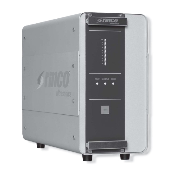
9 Operating controls and indicators Handles The generator insert module can be pulled out by these handles if necessary. Never pull out or insert the generator insert module while the unit is connected to the mains. Power bar Indicates the power delivered during the welding process. -
Page 20: Connection Of The Generator
Only original RINCO ULTRASONICS AG components must be used for this. Otherwise the overall system may fail to work properly. -
Page 21: Description Of The Signals
10.2 Description of the signals AMPL_AIN The amplitude can be changed in real-time during wel- The available signals are briefly described below. The ding with the voltage from 3 - 10 V in the range from time behaviour of the signals is described in section 30 to 100%. - Page 22 10VDC is used for 120% of the rated generator output power. Example: POWER_AOUT (0 - 10 V) Generator Current power output in W Current power output in % Voltage at POWER_AOUT in V RDG20-2000 1600 6.67 RDG30-1000 1000 8.33 RDG35-900 3.33 RDG40-800 4.17...
-
Page 23: Sto_3
10.2.4 STO_3 START_1_AMP_IN This input can be used to start the welding process. 24VDC_EMERGENCY_IN The input is 'high active', i.e. ultrasonic operation is Emergency stop input. started if 24VDC is present at this input. TRIGGER_IN No function MV_OUT_ACTUATOR This NPN output can be used to actuate the solenoid This input needs to be activated by setting jumper J10. -
Page 24: Operating Modes
11. Operating modes 11.1 Welding mode The RDG generator can only be operated in conti- nuous mode. No time or energy monitoring is performed. 11.2 Power overload Power overload If the generator is operated for longer than 50 ms at a power above the maximum of 120% of the generator power, then the welding process is aborted with an error message in order to protect the oscillator system. -
Page 25: Frequency Lock-In Range
11.5 Frequency lock-in range The maximum frequency lock-in range (permitted range of the ultrasonic oscillator) is at +500 Hz and –500 Hz of the nominal frequency for 20, 30, 35 and 40 kHz generators and at +3000 Hz and -3000 Hz for 70 kHz generators. -
Page 26: Settings
12 Settings The dip switches and the jumper J6 are located on the UGI generator insert, and the jumpers J9 and J10 are located on the BUS PCB in the housing. The generator insert module must never be pulled out or inserted while the unit is connected to the mains. - Page 27 Dip switches - settings Ampl. Cable length SlowControl Amp 1 Amp 2 Amp 3 CabLen 1 CabLen 2 SlowControl N.C. N.C. 100% Dip switches OFF 11 m Analog In Examples: Standard settings Dip switches n.c. n.c. The standard settings of the RDG generator are used.
-
Page 28: Jumper J6
The counter pulse is only output if the welding cycle has been completed without errors. Example: PART_COUNT_OUT (0-4V) Generator Current power output in W Current power output in % Voltage at PART_COUNT_OUT in V RDG20-2000 1600 2.67 RDG30-1000 1000 3.33 RDG35-900 1.33 RDG40-800 1.67... -
Page 29: Amplitude Values
13 Amplitude values The different generator outputs produce different amplitudes. The amplitude value described in the table below refers to the configuration of the corresponding sonotrode/generator/booster combination. The effective welding amplitude can therefore be read off directly. 13.1 Amplitude values 20 kHz generators Sonotrode Converter Booster... -
Page 30: Amplitude Values For 30 Khz Generators
13.2 Amplitude values for 30 kHz generators Sonotrode Converter with integrated booster Amplitude Interface (converter/sonotrode) 13.2.1 Amplitude diagram for 30 kHz generators 500 W (converter C30-1) 1000 W (converter C30-2) 100% 100% 1:1.5 Integrated Horns booster Gain... -
Page 31: Amplitude Values For 35 Khz Generators
13.3 Amplitude values for 35 kHz generators Sonotrode Converter Booster Amplitude Interface (converter/booster) Interface (booster/sonotrode) 13.3.1 Amplitude diagram for 35 kHz generators... -
Page 32: Amplitude Values For 40 Khz Generators
13.4 Amplitude values for 40 kHz generators Sonotrode Converter with integrated booster Amplitude Interface (converter/sonotrode) 13.4.1 Amplitude diagram for 40 kHz generators 800 W (converter C40-2) 400 W (converter C40-2) 100% 100% 1:1.5 Integrated Horns booster Gain... -
Page 33: Amplitude Values For 70 Khz Generators
13.5 Amplitude diagram for 70 kHz genera- tors Sonotrode Converter Amplitude Interface (converter/sonotrode) 13.5.1 Amplitude diagram for 70 kHz generators 9 100% 7 90% 5 80% 3 70% 1:10 Sonotrode Sonotrode Sonotroden Sonotroden amplifi cation amplifi cation Verstärkung Verstärkung... -
Page 34: Example Applications
14 Example applications A number of example applications are presented below. Please contact RINCO ULTRASONICS AG if you require any additional information. Detailed information about the electrical installation can be found in section 5.3. In the example applications, the digital inputs and outputs are operated via an internal 24VDC supply voltage. -
Page 35: Sto_3 / Sto_5
14.1.2 STO_3 / STO_5 The diagram shows the basic circuit for starting ultrasonic operation via the digital input START_1_ AMP_IN. To start, the signal is set to 24VDC, and the signal needs to be set back to 0VDC to stop ultrasonic operation. -
Page 36: Time Diagram
14.1.3 Time diagram The end of welding was triggered by the input START_EXT_1 being set to 0VDC (continuous mode). The welding process was aborted due to an error: – Oscillator, generator or limit error Welding stopped by applying 24VDC to US_STOP_1_ US_STOP_1_IN must be present for 5 ms before the stop is executed. -
Page 37: Amplitude Selection
14.2 Amplitude selection Via the analogue input AMPL_AIN (3 to 10V), the amplitu- de can be externally varied from the start amplitude (30%) to 100%. If the analogue signal is below the value for the start amplitude (30%), the generator will report a fault. -
Page 38: Time Diagram
14.2.1 Time diagram The end of the welding cycle was triggered by set- ting the input START_EXT_1 to 0VDC. The end of welding was triggered by setting the input START_EXT_1 to 0VDC. Welding was aborted because of an error. – Oscillator, generator or limit error Welding is performed at 80% of the target amplitu- de (80% corresponds to 8VDC). -
Page 39: Power Measurement
14.3 Power measurement The analogue signal of the output POWER_AOUT (0 to 10VDC) can be tapped and used for arbitrary interpretation or control tasks. Here, the maximum value of 10VDC corresponds to a power output of 120% of the nominal power. As a result, 100% of the nominal power is represented by a voltage value of 8.33VDC. -
Page 40: Time Diagram
14.3.1 Time diagram The end of the welding cycle is triggered by setting the input START_EXT_1 to 0VDC. The welding is started at 80% of the target ampli- tude (8VDC) - this remains unchanged throughout the entire welding time. In the theoretical model, the power depends on the amplitude and remains constant in the process. -
Page 41: Technical Data
Sicherung F3 Fuse Sicherung F4 Fuse Generatortyp Sicherung F1 Fuse Sicherung F2 Fuse Generator type GENERATOR 5x20mm 5x20mm 5x20mm 5x20mm 6.3x32mm 5x20mm RDG20-2000P-230 12,5A 12,5A UGI20-2000P-230 12,5A RDG20-1500P-230 UGI20-1500P-230 RDG20-1000P-230 UGI20-1000P-230 RDG30-1000P-230 UGI30-1000P-230 RDG30-500P-230 UGI30-500P-230 RDG35-4-900P-230 6,3A 6,3A UGI35-4-900P-230 6,3A... -
Page 42: Overview Of Inputs And Outputs
15.3.2 Overview of inputs and outputs The following table shows an overview of inputs/outputs. Name Type Description Voltage level RESET_IN Input Error acknowledgement, 24VDC Input current stop = 5 mA typ. Weld cycle Input resistance = 8.2 kΩ US_ACTIVE_OUT Output Ultrasonic process active 24VDC = ultrasonic process active Output current = 100 mA max. -
Page 43: Analogue Input And Output
15.3.3 Analogue input and output Due to the circuit layout, the analogue input AMPL_ AIN has a delay of a maximum of 0.7 ms. The analogue power output also has a delay of 0.7 ms. To ensure that no errors occur at the analogue input, the internal resistance of the supply source must not exceed 330 AMPL_AIN input In order to prevent the generation of errors at the... - Page 44 15.3.4 Time behaviour of digital inputs and outputs The diagrams below show the time behaviour of the different inputs and outputs. START_EXT_1, US_STOP_1_IN, US_ACTIVE_OUT US_READY_OUT START_EXT_1_IN US_STOP_1_IN Parameter Condition Symbol Min. Nominal Max. Unit START_EXT_1_IN Pulse Width High US_ON_HI START_EXT_1_IN Pulse Width Low US_ON_LO US_STOP_1_IN Pulse Width High US_STOP_HI...
-
Page 45: Cleaning And Maintenance
16 Cleaning and maintenance The generator requires no maintenance. However, the converter, booster and sonotrode should be checked periodically and kept clean on the outside. 16.1 Periodic checks If a cooling fan is provided then it should be checked periodically (according to the operating environment) for dust and cleaned as required. -
Page 46: Disposal
17 Disposal The generator must be disposed of properly in accord- ance with the applicable legislation and requirements. Please contact RINCO ULTRASONICS AG for more information. -
Page 47: Error Messages And Error Analysis
18 Error messages and error analysis ERROR will light indica- te if an error is present. The connection between ERROR_24VDC_IN and ERROR_OUT is interrupted. In order make it easier to analyse the error, errors are classed in three groups which are indicated by flas- hing of the LEDs (LED1 to LED3) on the power bar. -
Page 48: Troubleshooting
19 Troubleshooting In the case of errors which do not originate in the application, always contact your nearest RINCO ULTRASONICS AG service centre. 19.1 General errors Error Error remedy Ready (green) LED - Check the mains voltage supply not lighting up - Check the fuse Actuation via digital - Check the voltage supply 24VDC_IO_IN... -
Page 49: Generator Error Led1
19.2 Generator error LED1 Error Cause Response Error remedy Mains voltage too - The mains voltage applied- - Error message - Check the mains voltage at the generator is generated. is below 85% of the - Ultrasonic process nominal voltage. is aborted. -
Page 50: Converter And Application Error Led2
19.3 Converter and application errors LED2 Error Cause Response Error remedy Minimum frequency - Oscillator system not - Error message is - Check cable connection limit violation connected generated - Check cable(s) - Oscillator system defective - Ultrasonic process is - Check/replace converter - Excessive damping of aborted... -
Page 51: Limit Error Led3
19.4 Limit error LED3 Error Cause Response Error remedy Maximum power - Power too high - Error message is generated - With this type of error, exceeded - Ultrasonic process is it is also vital to aborted reconsider the choice of - A new ultrasonic process is delay time started at the last... -
Page 52: Service Centre Addresses
20 Service centre addresses In the event of any technical faults or welding pro- blems please contact the RINCO ULTRASONICS AG technical customer service team, who will be pleased to help. To enable our service team to provide the best possib- le assistance we will need the following: –... - Page 54 RINCO ULTRASONICS AG Industriestrasse 4 CH-8590 Romanshorn 1 Switzerland Tel. +41 71 466 41 00 Fax +41 71 466 41 01 info@rincoultrasonics.com www.rincoultrasonics.com...
Need help?
Do you have a question about the RDG20 and is the answer not in the manual?
Questions and answers