
Summary of Contents for GAZ VALDAI GAZ33104
- Page 1 LIMITED LIABILITY COMPANY "AVTOZAVOD "GAZ" (LLC "AVTOZAVOD GAZ") VALDAI VEHICLES FAMILY OPERATING INSTRUCTIONS 33104 3902111 ИЭ RUSSIA NIZHNIY NOVGOROD...
-
Page 2: Introduction
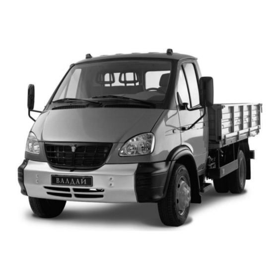
GAZ 33104 vehicle — 4x2 type with three seat cabin. GAZ 331041 vehicle — 4x2 type with three seat cabin and extended wheel base. GAZ 331043 vehicle — 4x2 type with six seat cabin and extended wheel base. -
Page 3: Vehicle Identification Data
1.VEHICLE IDENTIFICATION DATA Identification number of the vehicle (VIN) and identification numbers of cabin or all metal body, engine and cargo body vehicle chassis refer to the ve hicle identification data. Vehicle Identification Number (VIN) appears on the right frame side member before the rear spring front bracket (Fig.1.1). - Page 4 Chassis, cab and engine numbers refer to the identification data of chassis and special configuration vehicles for supplying to the other plants for making their own special vehicles having their own index. Nameplate "GAZ" is not installed and vehicle identification number does not appear on chassis and the...
-
Page 5: Useful Hints
LLC AUTOMOBILE PLANT GAZ “ “ ” 33104050140794 7500 кг кг 2400 кг 2- 540 кг Д-245.7Е2 ENGINE Fig. 1.4. Manufacture's Plate with Vehicle Identification Data, where: a — vehicle identification number; b — gross vehicle weight; c — gross vehicle weight with trailer;... -
Page 6: Safety Precaution Rules
5. If the engine has been operated at heavy duty cycle let it run for 3 min utes at idle speed before stopping to decrease smoothly the temperature of tur bocharger to avoid its premature damage. 6. To prevent damaging of the gearbox when towing the vehicle, discon nect the propeller shaft flange from the axle drive. -
Page 7: Specifications
4. SPECIFICATIONS 4.1. GENERAL DATA Vehicle model GAZ 33104 GAZ 331041 GAZ 331043 Vehicle type Biaxial, cargo, with rear axle drive Vehicle capacity, kg: — with cargo body without canvas top 3605 3445 3150 — with cargo body and with canvas top... - Page 8 Cylinder bore and piston stroke, mm 110x125 Displacement, l 4.75 Compression ratio Rated power, net, kW (h.p.), not less: at 2400 min engine speed 86.7 (117.2) Maximum torque, net, N•m (kgf•m): at 1300 1600 min engine speed 413 (42.1) Minimum engine idle speed, min Maximum idle speed limited by governor, min not more 2600...
-
Page 9: Running Gear
Final drive Bevel, hypoid type — transmission ratio 3.417 Differential Bevel, gear type Axle shafts Full floating 4.4. RUNNING GEAR Frame Stamped, riveted Wheels Disk type, with 6,00x17,5 rim Tires Pneumatic, radial, size 215/75R17,5 Front wheel geometry: — camber Max. 1° —... - Page 10 22.3721/221.3721 4.8. CABIN AND CARGO BODY Cabin Metal, three— or six seat Cargo body Metal, with rear flap and body sides Cargo body dimensions (inner), mm: GAZ 33104 GAZ 331041 GAZ 331043 — length 3494 5000 3494 — width 2176...
- Page 12 Positions of controls are given in fig. 5.1. 1 — headlamp aiming device control knob depending on vehicle loading (see subsection 8.5). 2 — plugs. 3 — warning lamps condition check up switch. 4 — side ventilation grids. 5 — turn indicators, dimmer and horn switch lever.
- Page 13 0 — all Off, the key cannot be pulled out, anti theft device is not engaged; I — engine control switch is On; the key cannot be pulled out; II — engine control switch and starter are On; the key cannot be pulled out; III —...
- Page 14 In case the control lever is equipped with horn switch (fig. 5.6), to turn on windshield wiper and washer momentarily push the lever from position 0 in the direction of arrow "A" and to turn on the horn pull the lever (from any position) in the direction of arrow "B".
- Page 15 To empty the ashtray pull it, push spring catcher upwards and remove the ashtray from its slot. Fit the ashtray back lifting up the spring catcher. 18 — gearbox lever. Engage reverse gear only after full stop of the vehicle. When reverse gear is engaged the backing light goes on in the tail lamps.
- Page 16 III — additionally (from position I or II) front fog lamps are ON. IV — additionally (from position III) rear fog light is ON. Fig. 5.11. Positions of master light switch handle. 23 — ABS diagnostics button. 24 — accelerator pedal. 25 —...
- Page 17 Fig. 5.13. Releasing of hood latch. To open the hood completely, move aside the latch mounted on the lower front edge of the hood (fig. 5.13). Arrangement of instruments is shown in Fig. 5.14. 10 11 12 13 14 Fig. 5.14. Instrument cluster. 1.
- Page 18 10. Warning lamp (green) of right turn indicators. 11. Warning lamp (red) of anti lock brake system (ABS) malfunction. 12. Warning lamp (red) of engine overheating. If the lamp lights up shut down the engine and eliminate the reason of over heating.
-
Page 19: Doors, Seats And Seat Belts
3. For driver's convenience seat tilt is also adjusted by means of nuts 1. GAZ 331043 vehicle is equipped with the second row of seats — two double seat passenger seats. Fig. 6.2. Driver Seat 1 —... - Page 20 To gain access to the rear passenger seats, the front passenger seat to be moved in the direction of the driver seat. This seat shifting mechanism is simi lar to that of the driver's seat. Before driving the vehicle shift the passenger seat to the extreme right position by all means, otherwise safety belt will be ineffective.
- Page 21 Warning! The belts which underwent critical loading in a road accident or they became frayed, cut and had other damages must be renewed by new ones in assembly. Never make any changes in the seat belt design. Never attempt to use the seat belt for more than one person. Keep hard or fragile objects such as glasses, fountain pens away from the belt as they may inflict additional injuries.
-
Page 22: New Vehicle Running In
7. New Vehicle Running in The running in duration is specified as 1000 km. During this period the vehicle requires special care and special servicing as well as the following rec ommendations should be strictly adhered to: 1. After starting until loading the engine, let it run for 2–3 minutes first at minimum idle speed with the gradual increase up to 1500 rpm. -
Page 23: Vehicle Operation
8. Vehicle Operation 8.1. ENGINE STARTING 8.1.1. Starting of cold engine Prior to engine starting check coolant level in engine cooling system and oil level in engine crankcase. When starting from cold, glow plugs bolting in stalled in cylinder heads turn on automatically. Engine cold starting is carried out in the following sequence: 1. -
Page 24: Vehicle Driving
8.1.2. Starting of cold engine at low temperatures At ambient air temperatures below –25° C (when the engine filled with low viscous oil) and below –15° C (when the engine filled with winter grade oils) the following methods of engine warming up are recommended prior to engine starting: a) engine heating with hot water. -
Page 25: Braking And Parking
When moving over the pools it is necessary to lower the speed to avoid hydroplaning, which may cause skidding and loss of control; the danger in creases with the tires worn. Drive the vehicle where possible without sharp acceleration and decelera tion for this will lead to the increasing tires wear and higher fuel consumption. -
Page 26: Heating And Ventilation Of The Cab
When stopping the vehicle on upgrade or slope, it is necessary to engage the parking brake and shift, respectively, into the first or reverse gear. To avoid freezing of the brake pads to the disks after a long driving over a wet road at sharp temperature variations, it is necessary to dry the pad linings by smooth braking when moving to the parking place. - Page 27 3 — handle of air temperature control in the cab (passenger compartment). The handle extreme left position (wide part of the blue symbol) activates the ventilation mode. The intermediate and extreme right positions (wide part of the red symbol) activate the heating mode. Defrosting and Demisting To remove quickly frost and condensate from the windscreen and door win dows do the following:...
-
Page 28: Lighting And Light Signaling Devices
— choose the mode of air distribution by turning handle 1; — turn handle 2 to get the desirable rate of the air flow coming to the pas senger compartment; — adjust the direction of air flows by turning the shutters of ventilation grids. - Page 29 Adjust the headlamps in the following sequence: — check air pressure in tires. Bring it, if necessary, to the required level; — place the unladen vehicle on a level ground at 5 m distance from the screen (Fig.8.5); — bring "0" on the handwheel into coincidence with the mark on the hous ing of the headlamp aiming device control unit;...
-
Page 30: Fuses
If, when switching on the turn indicators, its bulbs and pilot lamp do not light it means that fuse or turn indicator flasher unit (or its circuit) are faulty. Tail lamps. The vehicle is provided with the tail lamps including: braking lights, clearance lights, turn indicator lights, backing lights and fog lights. -
Page 31: Generator Set
Lower fuse box fuses protect the circuits of: 1. 25A — spare. 2. 15A — right headlamp main beam. 3. 15A — left headlamp main beam. 4. 10A — right headlamp dipper beam. 5. 10A — left headlamp dipper beam. 6. -
Page 32: Starter
from network exceeding 36 V. Carry out wire insulation check using megohm meter or lamp powered from network exceeding 36 V when alternator and reg ulator semiconductor devices are disconnected only. 5. Do not allow the direct water splashing on the alternator and regulator during vehicle washing. - Page 33 (CU) of ABS (in cabin at the right under the instrument panel), ABS diag nostic button (in the middle of the instrument panel), ABS failure warning lamp (on the right in the instrument cluster) and ABS harness connecting sen sors and input choppers with ABS CU. Two supply circuits are connected to ABS CU: for input choppers via 1st 25A fuse in the upper fuse block and direct for ABS CU via 11th 5A fuse in the upper fuse block.
-
Page 34: Towing Device
8.10 TOWING DEVICE Front and rear towing devices consist of towing fork with pivot bolt locked at below with cotter pin. Before towing the vehicle remove the front licence plate to make access to the towing fork. For towing the vehicle in heavy road conditions with small turning radiuses and so on, it is recommended to remove the bumper to pre vent its damage. -
Page 35: Checking Coolant Level
Fig. 9.2. Checking Oil Level in Rear Axle 1 — drain hole plug; 2 — filler hole plug Oil level in the rear axle (Fig. 9.2) should be to the level of the filler hole lower edge. 9.3. CHECKING COOLANT LEVEL Checking the coolant level in expansion tank 2 (Fig. -
Page 36: Checking Brake Fluid Level In Clutch Master Cylinder Tank
Fig. 9.4. Checking Brake Lining Wear Rate In Fig. 9.4 "A" "P" mark position is shown when the brake pads are new. When mark position corresponds to the position shown in Fig. "B", friction linings and brake disk thickness should be checked with the wheels removed. Moreover, brake pad wear indicator is installed in every disk brake to deter mine friction linings wear. -
Page 37: Checking Storage Battery Electrolyte Level
9.6. CHECKING STORAGE BATTERY ELECTROLYTE LEVEL Storage battery electrolyte level should be between MIN and MAX marks (Fig. 9.6) on the semi translucent battery housing and in case of their absence — to the lower edge of the filler hole. Fig. -
Page 38: Checking Oil Level In Power Steering Reservoir
The battery can be switched off or on also by immediate pressing on the switch button, covered with rubber cap. To avoid the damage of electric equipment it is not allowed to switch off the storage battery with the engine running. 9.7. -
Page 39: Wheels And Tires Care
9.9. WHEELS AND TIRES CARE In the process of vehicle operation it is necessary to timely tighten the loose wheel nuts to avoid damaging the fastening holes, remove rust from the wheels and restore their colour. To ensure maximum service life of the tires the following rules should be observed: —... -
Page 40: Changing A Wheel
9.10. CHANGING A WHEEL Replace the wheel in the following sequence: — apply the handbrake; — place chocks under the wheels from the side opposite to the wheel to be removed; — loosen six nuts of the wheel to be removed; —... -
Page 41: Cab Care
2. Do not work beneath the vehicle with the lifting jack as the only sup port. To carry out adjustment and mounting/dismounting operations lift the vehicle on the jack and then lower it on suitable stands. 3. In storage jack screw 2 should be driven all the way in, the operating and delivery plungers must take the lowermost position and shut off needle 7 be unscrewed through 1 or 2 revolutions. -
Page 42: Types Of Maintenance
On detecting corrosive spots it is necessary to remove the rust to pure metal, prime and apply corrosion resisting mastic. At frosty weather you should not wash the vehicle out of door or drive with wet or just washed cab, because by water freezing cracks may appear on painted surface. -
Page 43: Procedures Carried Out During Maintenance
9.13. PROCEDURES CARRIED OUT DURING MAINTENANCE 9.13.1. Daily Maintenance (EO) Tools and Procedure description Specifications materials Check the level of: — oil in engine crankcase See item 9.1 Visually — fluid in cooling system See item 9.3 Visually — fluid in clutch master See item 9.5 Visually cylinder tank —... -
Page 44: Periodic Maintenance (To 1, To 2, Co)
9.13.2. Periodic Maintenance (TO 1, TO 2, CO) Procedures for periodic maintenance are stated in the service book sup plied with the vehicle. 9.13.3. Vehicle Lubrication 1.Never use fuels, oils and liquids of other grades except for those specified in subsections 9.13.4 and 9.14. 2.Prior to lubrication remove dirt from grease nipples and plugs to avoid its penetration into the vehicle's mechanisms. - Page 45 Propeller shaft slip joint 200 g Oil "Супер Т 3". Substitute — oil "Девон Супер Т", "Лукойл ТМ5" SAE 85W 90 Intermediate propeller 50 g Grease Литол 24. Substitute — shaft bearing grease ЛИТА Steering knuckle pivot 30 g Solid oil Ж or solid oil C bearings Rear axle housing and At the temperature from –25°...
-
Page 46: Equivalents Of Fuels, Oils, Lubricants And Fluids
9.14. EQUIVALENTS OF RUSSIAN AND FOREIGN FUELS, OILS, LUBRICANTS AND FLUIDS Russian fuel, oil, lubricant, Foreign fuel, oil, lubricant, Recommended t° ranges, °C fluids fluids (ambient) Diesel oil Л 0,5 2D (ASTM975 81) Above 0° C З 0,5 35 1D (ASTM975 81) From 0°... -
Page 47: Parts To Be Replaced On The Vehicle During Maintenance
Power steering oil Oil grade "A" For tropic climatic zone Oil grade "P" ISO 6074 HM 22 From –35° C to +45° C Spindle oil АУ ISO 6074 HH 22 From –25° C to +45° C Oil ВМГЗ ISO 6074 HV 15 For cold climatic zone Shock absorber fluid АЖ... - Page 48 Fig. 9.12. Fine Fuel Filter Element Replacement: 1 — filter cover; 2 — filter element; 3 — fil ter body; 4 — plug — unscrew plug 3 (Fig. 9.13) on fuel pump housing to bleed air and un screw union 1 by 1–2 turns on the fine fuel filter; —...
- Page 49 3. Oil filter, solid, replaceable. Filter designation is ФМ009 1012005. When installing the filter, lubricate the rubber gasket with engine oil and screw the filter onto the engine cylinder block. As soon as the gasket touches the cylinder block, add more 3/4th of the turn.
-
Page 50: Supplements
10. Supplements Supplement 1 10.1. FILLING CAPACITIES Fuel tank, Engine cooling system, l 21,5 Engine oil system, l Gearbox case, l Rear axle housing, l Power steering system, l Shock absorbers (each), cm 137,5 Clutch hydraulic drive system, l Lubricant for front wheel hubs (both), g 400±30 Lubricant for rear wheel hubs (both), g Windscreen washer tank, l... -
Page 51: Rolling Bearings Used On The Vehicle
Purpose and location Type Quantity Cab dome lamp for vehicles with two bank cab KЛУ9/ТБЦ 1 Control unit of head lamp aiming device A12 1,2 1 Instrument illumination control ACMH12 0,55 Heating and ventilation unit control desk A12 1,2 Cigar lighter socket lighting A12 1,2 Alarm switch pilot lamp A12 1,1... -
Page 52: Seals Used In The Vehicle
Type of bearing Bearing No. Quantity Location Steering gear Radial ball bearing 6 930904FT1C17 Steering column Needle roller bearing with one 904700УС17 Steering gear shaft pivot outer race joints Running gear Single row taper roller bearing 4 807813A Outer support of rear wheel Single row taper roller bearing 6 7515A Inner support of rear wheel... -
Page 53: Tightening Torques Of Most Important Junctions
Supplement 5 10.5. TIGHTENING TORQUES OF MOST IMPORTANT JUNCTIONS Tightening torque, Junction description daN·m (kgf·m) Tension bolts of: Cylinder head 19–21 Main bearing caps 20–22 Flywheel 18–20 Crankshaft balance weights 12–14 Crankshaft pulley 24–28 Injection nozzles 2–2.5 Cardan drive flanges 12–16 Transfer drive reduction gear and drive pinion bearings clutch 9–11... -
Page 54: Table Of Contents
Contents Page Introduction ............................. 2 1. Vehicle Identification Data ..................... 3 2. Useful Hints ..........................5 3. Safety Precaution Rules ......................6 4.Specifications ..........................7 5. Controls and Instruments ..................... 11 6. Doors, Seats and Seat Belts ....................19 7. New Vehicle Running in ....................... 22 8. - Page 55 10. Supplements ..........................50 10.1. Filling Capacities ......................50 10.2. Electric Bulbs Used ....................50 10.3. Rolling Bearings Used on the Vehicle ..............51 10.4. Seals Used in the Vehicle ..................52 10.5. Tightening Torques of Most Important Junctions ..........53 Отпечатано...