Table of Contents
Advertisement
Advertisement
Table of Contents

Summary of Contents for logika HMD-SM
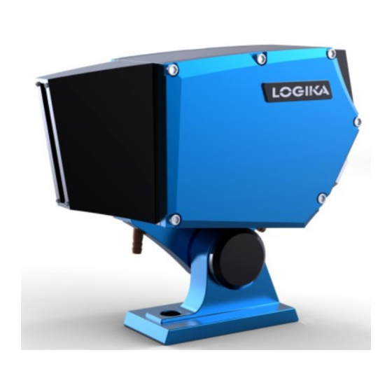
- Page 1 Scanning Hot Metal Detector HMD-SM Operator’s Manual Revision 2.1...
-
Page 2: Table Of Contents
5.4 Test Function ........................ 13 5.5 Troubleshooting ......................13 6. Maintenance ........................14 6.1 Regular Maintenance ....................14 6.2 Returns of the HMD-SM ....................15 7. Accessories- Hot Metal Simulation Test Bar..............15 8. HMD-SM Enclosure Dimensions ..................17 Web: www.logikatech.com... -
Page 3: Introduction
It includes a rugged enclosure, protecting state-of-the-art electronics and will withstand the harsh ambient conditions present in heavy industrial environments. The HMD-SM is used to detect hot metal in a range of temperatures, shapes and sizes of wire, bar, strip, thin plate, thick plate, billet, and slab production facilities. -
Page 4: Specifications
Table 2 2.3 Operating Principle Detector- The HMD-SM uses a Lead Sulfide (PbS) photocell, which is characterized by a very strong signal output for the range of infrared energy emitted by steel, compared with other detector materials. The high signal-to-noise ratio from this detector virtually eliminates detection errors. - Page 5 Figure 2.2: HMD-SM Scanning System Vertical Scanning field- The HMD-SM is manufactured with one of three vertical field angles 10, 30 and 50 degrees, selected at the time of purchase. This enables the sensor to cover the entire process area but not scan beyond the process line where interfering sources of infrared energy may be present.
-
Page 6: Automatic Threshold Level Adjustment
4 meters (13’) from the front of the located 4 meters (13’) from the front of the HMD with a HMD-SM-30 detector selected 30 detector selected, the vertical scanning field is 2.10 meters 2.10 meters or 84 inches. -
Page 7: Location And Mounting
1. Select the appropriate scanning angle when originally placing order to avoid “over- scanning”. 2. Gradually reduce the sensitivity adjustment on the HMD-SM’s control panel until the background interference is not detected (when no target metal is within the scanning field). -
Page 8: Sensor Mounting
Purge Air, Cooling Water- The HMD-SM has a water-cooling jacket to cool down sensor temperature and an air-purged shroud for protection of lens; allowing the sensor to be used in harsh environments with high temperatures, steam, dust and smoke. - Page 9 Logika Technologies Inc. Model HMD-SM Operator’s Manual Rev 2.1 Dec- Static Transistor Output- • PNP: Terminal 4B White, 24VDC on detect, maximum current 100 mA • NPN: Terminal 4A Black, 0VDC on detect, maximum current 100mA • Output Response time:...
-
Page 10: Cooling Water Connection
C o m m o n Y e l l o w / G r e e n G r o u n d Figure 4.1: HMD-SM Wiring Diagram 4.2 Cooling Water Connection Description- When the ambient temperature is higher than 50... -
Page 11: Purge Air Connection
Φ10mm ID (or 3/8” ID) hose. Purge air flows out of the sensor shroud and dissipates into the ambient environment. 5. Operation 5.1 Control Panel The HMD-SM Sensor’s Control Panel is located at the rear of the enclosure. The following functions are available on the Control Panel, see Figure 5.1. Web: www.logikatech.com Phone: 905-829-5841 Fax: 905-829-8787 Email: info@logikatech.com... -
Page 12: Automatic Threshold Level Description
Figure 5.1: HMD-SM Control Panel 5.2 Automatic Threshold Level Description Definition- The HMD-SM includes an Automatic Threshold Level Adjustment. The sensor’s built in circuit will automatically adjust the signal output when hot metal enters scanning field to prevent detect signal from saturation. According to different field applications, base threshold signal level is determined on installation. -
Page 13: Remote Threshold Sensitivity
C (480 F-750 Base Threshold Level Adjustment Procedure 1. Align the HMD to the target or put Logika Hot Metal Simulation Test Bar in the HMD-SM’s scanning field. 2. Normal (N) Sensitivity • Flip the sensitivity toggle switch to N •... -
Page 14: Test Function
Figure 5.2 HMD Remote Sensitivity Setup and Wiring Diagram 5.4 Test Function To test the electrical integrity of the HMD-SM sensor, follow the steps below: Connect power supply to the HMD-SM, make sure the green LED is ON. Press and hold the “TEST” button when no target in the scanning field of view. -
Page 15: Maintenance
Diagnostics- Usually, the HMD-SM does not need special maintenance. Regular attention to the following will ensure steady operation of the sensor: Lens Cleaning- periodically check the HMD-SM sensor’s glass for dust or oil residue, like a month or 2 months depended on the sensor’s environment and purge air quality. Open the black lens shroud and clean the glass with alcohol and lens paper or soft cloth. -
Page 16: Returns Of The Hmd-Sm
Oakville, ON, L6J 7J9 Canada Do not return the HMD-SM without a return authorization number. If the product is out of warranty, we will provide a repair estimate and then complete the repairs upon your approval. 7. Accessories- Hot Metal Simulation Test Bar... - Page 17 Logika Technologies Inc. Model HMD-SM Operator’s Manual Rev 2.1 Dec- Figure 7.1: Hot Metal Simulation Test Bar Drawing Web: www.logikatech.com Phone: 905-829-5841 Fax: 905-829-8787 Email: info@logikatech.com P a g e | 16...
-
Page 18: Hmd-Sm Enclosure Dimensions
Logika Technologies Inc. Model HMD-SM Operator’s Manual Rev 2.1 Dec- 8. HMD-SM Enclosure Dimensions All units are in mm Figure 8.1: HMD-SM Enclosure Side View Web: www.logikatech.com Phone: 905-829-5841 Fax: 905-829-8787 Email: info@logikatech.com P a g e | 17... - Page 19 Logika Technologies Inc. Model HMD-SM Operator’s Manual Rev 2.1 Dec- Figure 8.2: HMD-SM Enclosure front View Figure 8.3: HMD-SM Enclosure top View Web: www.logikatech.com Phone: 905-829-5841 Fax: 905-829-8787 Email: info@logikatech.com P a g e | 18...
- Page 20 Logika Technologies Inc. Model HMD-SM Operator’s Manual Rev 2.1 Dec- Figure 8.2: Junction Box Dimension Web: www.logikatech.com Phone: 905-829-5841 Fax: 905-829-8787 Email: info@logikatech.com P a g e | 19...
Need help?
Do you have a question about the HMD-SM and is the answer not in the manual?
Questions and answers