Advertisement
Quick Links
Advertisement

Summary of Contents for Alaron MTP-8010
- Page 1 3 PHASE TESTER & MOTOR ROTATION TESTER MTP-8010 INSTRUCTION MANUAL...
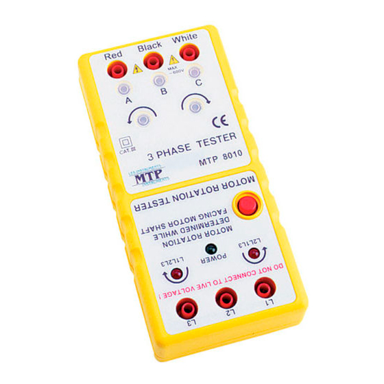
- Page 2 3 PHASE TESTER & MOTOR ROTATION TESTER (1) PHASE ROTATION INPUT TERMINAL (2) OPEN PHASE INDICATOR (3) PHASE ROTATION INDICATOR (4) MOTOR TESTER POWER SWITCH (5) MOTOR TESTER POWER INDICATOR (6) MOTOR ROTATION INDICATOR (7) MOTOR ROTATION INPUT TERMINAL...
- Page 3 Fig.1 Fig.2...
- Page 4 1. Introduction NOTE This meter has been designed and tested according to IEC Publication 348, Safety Requirements for Electronic Measuring Apparatus, IEC 1010 (En61010) and other safety standards. Follow all warnings to ensure safe operation. CAUTION READ "SAFETY NOTES" (NEXT PAGE) BEFORE USING THE METER.
-
Page 5: Safety Notes
2. Safety Notes Read the following safety information carefully before attempting to operate or service the meter. Use the meter only as specified in this manual; otherwise the protection provided by the meter may be impaired. Rated environmental conditions : (1) Indoor use. - Page 6 3. Features Three functions in one unit, including open phase, phase sequence and motor rotation indication. This model is ideal for installing conveyor lines, pump systems and interconnected drivers. Identifies 3-phase sequence and open phase check. Battery operated. Meets IEC 1010(EN61010) safety requirements. Comply with three large alligator clips.
-
Page 7: Measuring Methods
4. Measuring Methods Operation of 3 Phase Rotation Tester : (1) Connect the test lead to 3-phase input terminals by R-S-T. (2) Connect color alligator clips to the terminals of a 3- phase power source. Connecting order is optional. (3) Make sure that all of the three lamps for open phase check are on. - Page 8 If the counter clockwise indicator is lit, alternate the connection two of the three alligator clips. When the clockwise indicator is lit and the power source terminals are connected by the RED, YELLOW and BLUE alligator clips, the Phase Sequence Indicators (R, S and T) shall be lit respectively.
- Page 9 Rotate the motor shaft counter clockwise. If counter clockwise indicator is lit, it means there is a 3-phase motor connection to the power supply by L1-L2-L3. The 3-phase motor should be rotated clockwise. (4) If you require the motor to rotate counter clockwise, you should change the connection to L1-L2-L3.
-
Page 10: Specifications
5. Specifications Input Voltage : 100V AC up to 600V AC max. Frequency : 45 to 70 Hz. Circuit Structure : All electronic (not mechanical). Power Requirement : 006P DC9V battery. Power Consumption : Consumption current approx. 14mA of motor rotation field of tester. -
Page 11: Maintenance
6. Maintenance Battery Replacement : (1) It is necessary to replace battery, when green lamp is dull lit. (2) Use a screwdriver to unscrew the screw on the back then open the case(Fig.2), remove the battery and replace with new battery (type 006P, DC9V). - Page 12 If the meter is not in use for periods of longer than 60 days, remove the battery and store them separately.
Need help?
Do you have a question about the MTP-8010 and is the answer not in the manual?
Questions and answers