Table of Contents
Advertisement
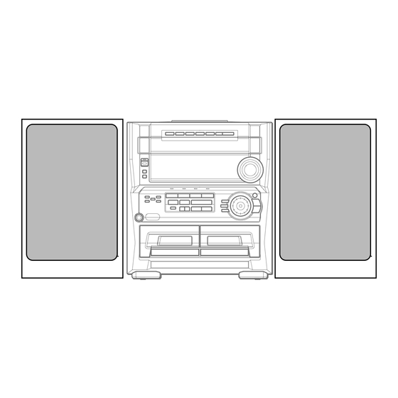
SERVICE MANUAL
COMPACT DISC STEREO
CASSETTE RECEIVER
SYSTEM
Z–HK550
• This Service Manual is the "Revision Publishing" and replaces "Simple Manual"
Z-HK550 (HR), (S/M Code No. 09-005-428-5T1).
• If requiring information about the CD mechanism, see Service Manual of
6ZG-1, (S/M Code No. 09-001-338-7N4).
Z-HK550
BASIC TAPE MECHANISM : ZZM-3 PR1NM
BASIC CD MECHANISM : 6ZG-1 VZRDM
CD
SPEAKER
CASSEIVER
CX–ZHK550
SX–WZHK550
S/M Code No. 09-005-428-5R1
HR
REMOTE
CONTROLLER
RC–ZAS07
Advertisement
Table of Contents

Subscribe to Our Youtube Channel
Related Manuals for Aiwa Z-HK550


Summary of Contents for Aiwa Z-HK550
- Page 1 SX–WZHK550 RC–ZAS07 • This Service Manual is the "Revision Publishing" and replaces "Simple Manual" Z-HK550 (HR), (S/M Code No. 09-005-428-5T1). • If requiring information about the CD mechanism, see Service Manual of 6ZG-1, (S/M Code No. 09-001-338-7N4). S/M Code No. 09-005-428-5R1...
-
Page 2: Specifications
SPECIFICATIONS <FM tuner section> <Compact disc player section> Tuning range 87.5 MHz to 108 MHz Laser Semiconductor laser (λ =780 nm) Usable sensitivity (IHF) 13.2 dBf D-A converter 1 bit dual Antenna terminals 75 ohms (unbalanced) Signal-to-noise ratio 85 dB (1 kHz, 0 dB) Harmonic distortion 0.05 % (1 kHz, 0 dB) <AM tuner section>... -
Page 3: Protection Of Eyes From Laser Beam During Servicing
PROTECTION OF EYES FROM LASER BEAM DURING SERVICING This set employs laser. Therefore, be sure to follow carefully CAUTION the instructions below when servicing. Use of controls or adjustments or performance of proce- dures other than those specified herin may result in WARNING!! hazardous radiation exposure. -
Page 4: Note On Before Starting Repair
NOTE ON BEFORE STARTING REPAIR 1. Forced discharge of electrolytic capacitor of power supply block When repair is going to be attempted in the set that uses relay circuit in the power supply block, electric potential is kept charged across the electrolytic capacitors (C101, 102) even though AC power cord is removed. - Page 5 In such a case, check also if the POWER AMPLIFIER circuit or power supply circuit has any abnormalities or not. 2-2. Regarding reset There are cases that the machine does not work correctly because the MICROCOMPUTER is not reset even though the AC power cord is re-inserted, or the software reset (pressing the STOP key + POWER key) is performed.
-
Page 6: Electrical Main Parts List
ELECTRICAL MAIN PARTS LIST REF. NO. PART NO. KANRI DESCRIPTION REF. NO. PART NO. KANRI DESCRIPTION 87-010-263-080 CAP, ELECT 100-10V 87-010-197-080 CAP, CHIP 0.01-25 8A-MG5-656-010 C-IC,LC876580W-5R45 87-010-247-080 CAP, ELECT 100-50V 87-A21-417-010 IC,STK490-340 87-010-406-080 CAP, ELECT 22-50V 87-A21-396-010 IC,STK490-040 87-010-381-080 CAP, ELECT 330-16V 87-A21-021-040 C-IC,BU2099FV 87-A20-783-040... - Page 7 REF. NO. PART NO. KANRI DESCRIPTION REF. NO. PART NO. KANRI DESCRIPTION C391 87-010-319-080 C-CAP,S 56P-50 J CH C785 87-010-197-080 CAP, CHIP 0.01-25KB C392 87-010-319-080 C-CAP,S 56P-50 J CH C786 87-010-197-080 CAP, CHIP 0.01-25KB C393 87-010-319-080 C-CAP,S 56P-50 J CH C788 87-010-149-080 C-CAP,S 5P-50 CH...
- Page 8 REF. NO. PART NO. KANRI DESCRIPTION REF. NO. PART NO. KANRI DESCRIPTION CN602 87-A60-131-010 CONN,6P V FE C305 87-010-196-080 CHIP CAPACITOR,0.1-25 CNA1 8A-NF8-653-010 CONN ASSY,9P TID-A(480) C306 87-010-196-080 CHIP CAPACITOR,0.1-25 CNA2 8A-NF6-640-010 CONN ASSY,3P (VM) ANF-6 C310 87-010-196-080 CHIP CAPACITOR,0.1-25 CN606 87-099-566-010 CONN,7P TUC-P7P-B1...
- Page 9 REF. NO. PART NO. KANRI DESCRIPTION REF. NO. PART NO. KANRI DESCRIPTION LED682 87-A40-619-040 LED,SLR-56PT-T31-W GRN C218 87-010-260-080 CAP, ELECT 47-25V LED683 87-A40-619-040 LED,SLR-56PT-T31-W GRN C221 87-010-405-080 CAP, ELECT 10-50V LED684 87-A40-619-040 LED,SLR-56PT-T31-W GRN C222 87-010-405-080 CAP, ELECT 10-50V LED685 87-A40-619-040 LED,SLR-56PT-T31-W GRN C223...
-
Page 10: Chip Resistor Part Code
REF. NO. PART NO. KANRI DESCRIPTION C105 87-A11-148-080 CAP,TC U 0.1-50 Z F C106 87-A11-148-080 CAP,TC U 0.1-50 Z F C107 87-A11-148-080 CAP,TC U 0.1-50 Z F C108 87-A11-148-080 CAP,TC U 0.1-50 Z F C109 87-A11-148-080 CAP,TC U 0.1-50 Z F C110 87-A11-148-080 CAP,TC U 0.1-50 Z F... -
Page 11: Transistor Illustration
TRANSISTOR ILLUSTRATION E C B B C E E C B 2SB1370 CD1585 DTC114ES CSA952 CSC4115 KTA1266 KTC3198 KTC3199 KRA102 2SA1235 2SJ461-T1 KRA104 2SK2158 2SC2714 KRA107 2SC3052 KRC102 2SD1306 RT1P141C CMBT5401 – 11 –... - Page 12 WIRING – 1 (MAIN / VM / KEY CON) – 12 –...
- Page 13 SCHEMATIC DIAGRAM – 1 (MAIN 1 / 3: AMP SECTION / VM) – 13 –...
- Page 14 SCHEMATIC DIAGRAM – 2 (MAIN 2 / 3: DECK SECTION / KEY CON) – 14 –...
- Page 15 SCHEMATIC DIAGRAM – 3 (MAIN 3 / 3: TUNER SECTION) – 15 –...
- Page 16 WIRING – 2 (MICON) – 16 –...
- Page 17 SCHEMATIC DIAGRAM – 4 (MICON / DECK) – 17 –...
- Page 18 WIRING – 3 (CNTL / KEY CD / MIC) – 18 –...
- Page 19 SCHEMATIC DIAGRAM – 5 (CNTL / KEY CD) – 19 –...
- Page 20 WIRING – 4 (AMP 1F) – 20 –...
- Page 21 SCHEMATIC DIAGRAM – 6 (AMP 1F) – 21 –...
- Page 22 WIRING – 5 (PT) – 22 –...
-
Page 23: Schematic Diagram - 7 (Pt)
SCHEMATIC DIAGRAM – 7 (PT) – 23 –... - Page 24 WIRING – 6 (DECK) FROM B MICON C. B CN104 J DECK C . B FC104 – 24 –...
-
Page 25: Ic Block Diagram
IC BLOCK DIAGRAM – 25 –... - Page 26 – 26 –...
- Page 27 FL (BJ746GNK) GRID ASSIGNMENT & ANODE CONNECTION GRID ASSIGNMENT – 27 –...
- Page 28 ANODE CONNECTION – 28 –...
- Page 29 IC DESCRIPTION IC, LC876580W-5R45 Description Pin No. Pin Name M-CLK Main IC control serial CLOCK output. M-DATA Main IC control serial DATA output. M-STB Common serial strobe. O-PLL-CE TUNER PLL IC control CHIP ENABLE output. SR-LCK SHIFT REGISTER IC control LATCH CLOCK output. RYM-CS RHYTHM IC chip select.
- Page 30 Description Pin No. Pin Name P27/RHYTHM FL segment P27 output/RHYTHM setting switching input. H: Present (Not used). P26/K-CON FL segment P26 output/KEYCON function detection. P25/SVCD FL segment P25 output/Super VCD detection (Not used). P24/ECO FL segment P24 output/ECO setting switching input. H: ECO mode off. 60, 61 P23, P22 FL segment P23, P22 output.
- Page 31 ADJUSTMENT <TUNER / DECK / MICON> MAIN C.B SFR352 SFR351 L802 L801 (DC BALANCE) IC801 (DC BALANCE) L951 TP2 (CLK) (3/3) (1/3) TP1 (VT) FFE831 TP5 (LCH) TP6 (RCH) MICON C.B FL101 IC101 L101 (O-KSCAN) TP8(GND) DECK C.B DECK–1 P HEAD DECK–2 R/P/E HEAD SFR1 –...
- Page 32 < TUNER SECTION > < DECK SECTION > 1. Clock frequency Check 8. Tape Speed Adjustment (DECK 2) Settings : • Test point : TP2 (CLK) Settings : • Test tape : TTA–100 Method : Set to AM 1602kHz and check that the test point is •...
-
Page 33: Mechanical Exploded View
MECHANICAL EXPLODED VIEW 1 / 1 – 33 –... -
Page 34: Mechanical Parts List
19 8A-MA5-034-010 PANEL,CD 54 8A-MA3-046-010 PANEL,SIDE R 3 20 8A-MG5-037-010 PANEL ASSY,TRAY VCD 5 55 8A-MA3-045-010 PANEL,SIDE L 3 21 87-B00-002-010 BADGE,AIWA 30 ABS SIL 56 87-MA3-062-010 FOOT, H17 22 87-NF4-216-010 HLDR,LOCK 1 A 87-078-060-010 BVIT3PB+3-10 23 8A-MA3-093-010 KNOB ASSY,RTRY JOG... -
Page 35: Tape Mechanism Exploded View
TAPE MECHANISM EXPLODED VIEW 1 / 1 TERMINAL, TERMINAL,LB1 IC, EW732 IC, EW732 P.C.B – 35 –... -
Page 36: Tape Mechanism Parts List
TAPE MECHANISM PARTS LIST 1 / 1 REF. NO. PART NO. KANRI DESCRIPTION REF. NO. PART NO. KANRI DESCRIPTION 8Z-ZM3-227-010 BELT,MAIN M3 8Z-ZM3-233-010 SPR-T,BRG M3 8Z-ZM3-235-010 BELT,MAIN L 84-ZM2-227-310 SPR-C,AZIMUTH 8Z-ZM1-235-010 PULLEY,MOT 87-A90-403-110 HEAD,RPH MS15R 87-045-347-010 MOT,SHU2L 70 87-A90-404-010 HEAD,EH LE15B 8Z-ZM1-232-010 GEAR,IDL FF/REW 8Z-ZM3-239-010... - Page 37 SPEAKER DISASSEMBLY INSTRUCTIONS Type.1 Type.4 Insert a flat-bladed screwdriver into the position indicated by the TOOLS arrows and remove the panel. Remove the screws of each speaker 1 Plastic head hammer unit and then remove the speaker units. 2 (() flat head screwdriver 3 Cut chisel How to Remove the PANEL, FR Type.2...
-
Page 38: Accessories / Package List
SPEAKER PARTS LIST SX-WZHK550 (YJ7SL) REF. NO. PART NO. KANRI DESCRIPTION 1 8Z-MS3-010-010 PANEL,FR 550 2 8Z-MS4-003-010 PROTECTOR 3 8Z-MS2-601-010 SPKR,W 200 4 8A-MS3-603-010 SPKR,M 120 5 88-MS1-608-010 SPKR,CERAMIC 6 88-NS3-605-010 CAP, 7 88-MS1-610-010 CORD,SPKR 8 88-NS5-611-010 CORD,SPKR B/L ACCESSORIES / PACKAGE LIST REF. - Page 39 2–11, IKENOHATA 1–CHOME, TAITO-KU, TOKYO 110, JAPAN TEL:03 (3827) 3111 9420208 9630472 0251431 Printed in Singapore...
Need help?
Do you have a question about the Z-HK550 and is the answer not in the manual?
Questions and answers