
Related Manuals for Giant-Vac Giant-Mow M4815KAWV


Summary of Contents for Giant-Vac Giant-Mow M4815KAWV
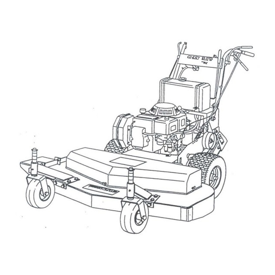
- Page 1 ASSEMBLY INSTRUCTIONS OPERATOR’S MANUAL PARTS LIST ‘Giant-Mow’ Walk-Behind Mower 48” Models covered: cut models M4815KAWV M4816BS-E Actual product may differ slightly from product pictured above Manual No. 3079199 (1/2003)
- Page 2 This page intentionally blank GVTP GM48-R0103.1...
-
Page 3: Model Number
preliminaries Congratulations! You have just purchased one of the finest pieces of outdoor power equipment on the market today. If properly cared for, your new mower will provide years of dependable service. Please read and follow this instruction manual carefully in order to get the most out of your new equipment. As you carefully uncrate your unit, you will find the following items: Mower Unit Caster Kit including:... -
Page 4: Operation
safety rules regarding outdoor power equipment PLEASE READ THE FOLLOWING BEFORE ASSEMBLING OR OPERATING UNIT • Be sure transmission is in neutral and cutting TRAINING blades are disengaged before starting engine. • Read, understand, and follow all instructions in the •... -
Page 5: Slope Operation
safety rules regarding outdoor power equipment (cont.) • Never allow children to operate the unit. SLOPE OPERATION • Use extra care when approaching blind corners, Slopes are a major factor related to loss-of-control shrubs, trees, or other objects that may obscure and tip-over accidents, which can result in severe vision. -
Page 6: Caster Assembly
safety rules regarding outdoor power equipment (cont.) • Grass catcher components are subject to wear, service procedures result hazardous damage, and deterioration, which could expose operation, equipment damage and voiding of moving parts or allow objects to be thrown. manufacturer’s warranty. Frequently check components and replace with manufacturer’s recommended... - Page 7 unit assembly (cont.) DISCHARGE DEFLECTOR ASSEMBLY • Attach discharge deflector (1:8) using two 5/16" x ¾" bolts and lock nuts (1:9-10). CAUTION: Do not over tighten lock nuts. TRANSMISSION SHIFT LEVER ASSEMBLY • Install Shift indicator panel (2:48) onto rear of engine deck (2:1) with two 5/16 x 3/4”...
-
Page 8: Fuel Tank Assembly
unit assembly (cont.) TRANSMISSION SHIFT LEVER ASSEMBLY (cont.) • Position ‘double-D’ hole in bottom leg of shift lever onto transmission stud, then slowly move handle of shifter back and forth until hole drops onto matching base of stud. • Replace washer and nut onto transmission stud. -
Page 9: Handle Assembly Installation
unit assembly (cont.) HANDLE ASSEMBLY INSTALLATION • Install handle assembly (4:1) to upper portion of engine deck using four 1/2" x 1-1/4" hex bolts, lock washers and nuts (4:3,5-6), with two flat washers (4:4) at slotted holes. Adjust for most comfortable operation, then tighten securely. -
Page 10: Battery Installation
unit assembly (cont.) BATTERY INSTALLATION *Important Note: Battery must be filled with acid before installation, as batteries are shipped dry for safety purposes. Battery acid can be obtained from any auto parts store. Do not overfill. • Remove hardware securing battery box cover (5:3) to battery box, and remove cover. -
Page 11: Starting The Engine
unit operation STARTING THE ENGINE IMPORTANT NOTE: The procedures outlined within this section are general guidelines, and are in no way meant to replace or supercede engine manufacturer’s operating instructions. In order to obtain optimum performance from your engine, refer to your engine manual. BEFORE STARTING ENGINE: •... -
Page 12: Mower Operation
unit operation (cont.) TO SHUT ENGINE DOWN: • Allow engine to idle for 2-3 minutes before shutting down. • Set throttle control to ‘slow’ position. • Turn ignition key to ‘off’ position. • If engine is not to be started for a prolonged period, turn fuel valve to closed position. IMPORTANT NOTE: If you experience problems with your engine that cannot be satisfactorily resolved by following the instructions contained within the engine manual, contact your local engine dealer, or call the toll-free service number listed in the repair section of the engine manual. -
Page 13: Engaging The Transmission
unit operation (cont.) ENGAGING THE CUTTING BLADES: Note: Never engage the mower blades until you are ready to mow and be certain to disengage them when finished. Never attempt any adjustment or repairs when the blades are engaged. • To engage the cutting blades, simply flip the blade engage switch (4:32), located on the left side of the handle dash, up to the ‘engage’... -
Page 14: Steering The Unit
unit operation (cont.) • Move the shift lever to first gear (‘1’), unlock brakes, and slowly release the brake handles. • Your mower has five forward speeds (‘1’ – ‘5’); simply slide the shifter lever to the appropriate indicator position to select that gear. machine can be shifted on the run. - Page 15 maintenance GENERAL: • Follow implicitly the engine manufacturer’s recommendations for maintenance. • Always keep your machine clean - especially the engine deck. Check all adjustments periodically. Also, periodically check that all fasteners are secure. Remember, sharp blades cut better. Always have an extra set on hand.
-
Page 16: Troubleshooting
maintenance (cont.) TROUBLESHOOTING: • UNIT WILL NOT START: Check to make sure cutting blades are disengaged. Check to make sure transmission is in neutral. Check fuel and oil levels. Check to make sure throttle control engages engine choke when set to ‘start’ position; adjust if needed. Check all electrical connections for positive contact; repair or replace as necessary. - Page 17 maintenance (cont.) • THROTTLE CABLE ADJUSTMENT: Correct cable adjustment engages choke mechanism on engine when throttle control on handle dash is set all the way to right (‘Start’). To adjust, CHOKED 1/8 – 1/4” loosen cable clip screw on engine, then slide cable out approximately 1/8-1/4”.
- Page 18 maintenance (cont.) • BRAKE ADJUSTMENT: LOWER ROD - The brake assembly has been set at the factory. However, they periodically need adjustment. As a rule of thumb, the bottom bend of the lower brake rod (3:14) should be ADJUST 3/8” lower than the center of the pivot boss hole in the brake arm (3:5).
-
Page 19: Replacement Parts
DRIVE PULLEY ALIGNMENT: Check to see that drive pulleys are in line with side idler pulley and wheel drive pulley; adjust as needed by loosening set screw in pulley and realigning pulley. Retighten set screws to 150 in. lbs. REPLACEMENT PARTS: • Replacement parts are available through your Giant-Vac dealer. GVTP GM48-R0103.1... - Page 20 This page intentionally blank GVTP GM48-R0103.1...
- Page 21 To Blade Clutch - See Engine & Trans Group See Engine & Trans Group GIANT-VAC, INC. PARTS LIST #5807 'GIANT MOW' 48" Cut Models BLADE DECK GROUP SHEET 1 OF 6 R0103.1 thru A , C thru GVTP GM48-R0103.1...
- Page 22 Parts List #5807 Giant Mow 48” R0103.1 SHEET 1 - BLADE DECK GROUP REF # PART # DESCRIPTION 10246 Blade deck 79166 Decal – ‘Operating Rules 1-8’ 31895 Rubber hood strap (w/attaching hardware) 31100 3/16 pop rivet (attaches strap receiving cup to hood) 27134 Front bumper bar 31660...
- Page 23 Auxiliary blade belt 27424 Blade deck hood 31917 Mower hood edge trim – 72” length 79169 Decal – ‘Giant-Vac’ – 17” 79090 Decal – ‘Danger – Keep Hands & Feet Away’ 79088 Decal – ‘Danger – Flying Material’ 31890 2” rubber hood cap...
- Page 24 To Drive Wheel - See Side Idler & Axle Group To Ref #9 this sheet GIANT-VAC, INC. PARTS LIST #5807 'GIANT MOW' 48" Cut Models ENGINE & TRANS GROUP To Blade Pulleys - See Blade Deck Group SHEET 2 OF 6 R0103.1...
- Page 25 Parts List #5807 Giant Mow 48” R0103.1 SHEET 2 - ENGINE & TRANS GROUP REF # PART # DESCRIPTION 10245 Engine deck 39083 Engine – 15hp Kawasaki electric start 39116 Engine – 16hp Briggs & Stratton electric start 31589 8mm x 25mm hex bolt – 15hp Kawasaki 31294 5/16-18 x 1-1/2”...
- Page 26 Parts List #5807 Giant Mow 48” R0103.1 SHEET 2 - ENGINE & TRANS GROUP (cont.) REF # PART # DESCRIPTION 36154 2-V drive pulley 31439 5/16-18 x 1/4” socket set screw 36155 2-V drive belt 23264 Shift lever 31722 Handle grip - 1/4" x 1-1/4" x 4-1/2" 31461 1/2-13 x 2-1/2"...
- Page 27 See Engine & Trans Group See Handle Group 32 31 40 41 thru GIANT-VAC, INC. PARTS LIST #5807 'GIANT MOW' 48" Cut Models SIDE IDLER & AXLE GROUP SHEET 3 OF 6 R0103.1 GVTP GM48-R0103.1...
- Page 28 Parts List #5807 Giant Mow 48” R0103.1 SHEET 3 - SIDE IDLER & AXLE GROUP REF # PART # DESCRIPTION 33235 Axle assembly 27407 Brake pivot plate - left 27408 Brake pivot plate - right 31033 3/8" lock washer 31008 3/8-16 x 1 hex bolt 23152 Brake arm - left...
- Page 29 Parts List #5807 Giant Mow 48” R0103.1 SHEET 3 - SIDE IDLER & AXLE GROUP (cont.) REF # PART # DESCRIPTION 31009 3/8-16 hex nut 31088 5/16-18 x 3" hex bolt 31004 5/16-18 nut 31003 5/16 lock washer 31004 5/16-18 nut 31383 Rod fitting end (trunion) 31027...
- Page 30 GIANT-VAC, INC. See Side Idler & Axle Group PARTS LIST #5807 'GIANT MOW' See Engine & Trans Group 48" Cut Models HANDLE GROUP SHEET 4 OF 6 R0103.1 GVTP GM48-R0103.1...
- Page 31 Parts List #5807 Giant Mow 48” R0103.1 SHEET 4 - HANDLE GROUP REF # PART # DESCRIPTION 23127 Handle assembly 79092 Eye/ear/breathing decal 79089 Off/run/start decal 79112 Mower engage decal 79184 ‘Read owner’s manual’ decal 31283 Handle grip - 1"dia x 4-1/2" 31122 1/2-13 x 1-1/4"...
-
Page 32: Electrical Group
Wiring Scheme Battery ground bolt - See Engine & Trans Group Connects to Engine Starter See Engine & Trans Group GIANT-VAC, INC. PARTS LIST #5807 Blade Clutch - 'GIANT MOW' See Engine & Trans Group Engine - 48" Cut Models See Engine &... - Page 33 Parts List #5807 Giant Mow 48” R0103.1 SHEET 5 - ELECTRICAL GROUP REF # PART # DESCRIPTION 39058 Battery (12N14-3A) 31681 Rubber battery cover – 1/8*’ x 3” x 5” 40151 Battery box cover 31444 1/4-20 x 1” hex bolt 31098 1/4-20 lock nut 31662...
- Page 34 Ignition Switch 5-terminal female housing - Safety Switch 1/4" male - Safety Switch ground 1/4" ring terminal - GIANT-VAC, INC. bolts under handle dash 1/4" ring terminal - to battery positive stud PARTS LIST #5807 of Solenoid 90 deg 1/4" female -...
- Page 35 This page intentionally blank GVTP GM48-R0103.1...
- Page 36 Any obligation under this warranty is expressly limited to the replacement or repair, at an authorized servicing Giant-Vac dealer, or at a point designated by us, of such parts as appear to us to have been defective. All defective parts have to be returned freight prepaid before credit will be issued.
Need help?
Do you have a question about the Giant-Mow M4815KAWV and is the answer not in the manual?
Questions and answers