
Subscribe to Our Youtube Channel
Related Manuals for AVANT Aurora 90 Electric


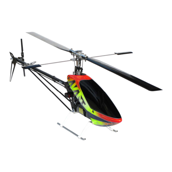
Summary of Contents for AVANT Aurora 90 Electric
-
Page 2: Liability Disclaimer
Aurora AVANT Electric 90 Assembly Manual urora AVANT 90 Electric Assembly Manual V2.01 LIABILITY DISCLAIMER This kit is for a radio controlled (RC) helicopter. RC Helicopters are not toys. Moving parts can present a hazard to operators, bystanders and anyone or anything that could be reached by the RC helicopter. Improper... - Page 3 Aurora AVANT Electric 90 Assembly Manual Before you start assembling: Get the latest manual: It’s highly recommended that you get the latest version of the manual. Please download a copy by clicking here and use that copy instead of this one.
- Page 4 Aurora AVANT Electric 90 Assembly Manual M3x8 (8) 26mm frame spacers (9) AV000108 Note: Unless indicated otherwise all screws, balls and threads are installed with Blue Loctite...
- Page 5 Aurora AVANT Electric 90 Assembly Manual Bag #2 M2.5x8 (6) M3x6 Button Head (6) M2.5 washer (6) AV900212 AV900211 AV900218 AV900224 Using six M2.5x8 screws install Using six M3x6 button head screws the Main gear onto the pre- install the constant drive gear onto assembled main gear hub the constant drive hub.
- Page 6 Aurora AVANT Electric 90 Assembly Manual M3x8 (2) AV000120 AV900239 AV000100 (3) Open bearing side faces up Note: This one is a Open bearing Button Head M3x8 side faces down Open bearing side faces up M3x8 (5) Note: Unless indicated otherwise all screws, balls and threads are installed with Blue Loctite...
- Page 7 Aurora AVANT Electric 90 Assembly Manual M3x8 (4) AV920354 AV000101 Make sure there is a flat AV000100 spot in the motor shaft for the M4 setscrew AV920354 AV920354 M3x4 Setscrew Button Head The motor and pinion stack assembly can slide.
-
Page 8: Very Important
Aurora AVANT Electric 90 Assembly Manual VERY IMPORTANT!!! READ AND FOLLOW THE TAIL GEAR MESH METHOD Failure to do so can cause the tail gears to fail in flight This is the method used to do a correct mesh on the Aurora tail gears. This applies to both the front set (the set inside the frames) and the back set (the set inside the tailcase). - Page 9 Aurora AVANT Electric 90 Assembly Manual Wrong alignment case #1: Wrong alignment case #2: Top gear too forward Bottom gear too forward Flush alignment is easily achieved because the kit brings four sets of three bearings spacing washers of 0.1, 0.2 and 0.3mm thickness. Combining them you can get from 0.1mm to 0.6mm spacing (0.1), (0.2),...
- Page 10 Aurora AVANT Electric 90 Assembly Manual 2) No Play: The second and very important thing to make sure you have is that there is absolutely no play between the gears. In order to make sure that there is no play between the gears hold one of the shaft firmly while trying to rotate the other one back and forth.
- Page 11 Aurora AVANT Electric 90 Assembly Manual Bag #3 Before inserting the M2 spring pin (black one) you can make it easier to insert it into the 2mm shaft hole by crimping the tip of the spring pin very slightly to make the tip of the pin sharper.
- Page 12 Aurora AVANT Electric 90 Assembly Manual AV900206 AV900216 AV000104 AV900243 Assemble the vertical pickup shaft as shown on the picture. M2 Spring Pin Note that the spring pin (black one) is the one above and the dowel pin (silver one) is M2 Dowel Pin the one at the bottom side.
- Page 13 Aurora AVANT Electric 90 Assembly Manual M3x8 (8) Note: Unless indicated otherwise all screws, balls and threads are installed with Blue Loctite...
- Page 14 Aurora AVANT Electric 90 Assembly Manual Bag #4 Canopy Post Short AV900217 M3 Locknut (2) M3x8 (2) M3x8 M3x8 M3x8 (2) Canopy Post Tab AV000102 AV920350 M3 Locknut Canopy Post Long AV900217 M3 washers (6) used on motor mount and pinion...
- Page 15 Aurora AVANT Electric 90 Assembly Manual Bag #5 AV000123 (5) AV000112 M2.5x8 M2.5 washer AV000111 Short CCPM spacer AV000137 M4x4 cup point Setscrew M4x4 cup point Setscrew AV000111 AV000123 AV000112 AV000123 (3) Long CCPM AV000111 spacer M4x4 Setscrew Note: Unless indicated otherwise all screws, balls and threads are installed with Blue Loctite...
- Page 16 Aurora AVANT Electric 90 Assembly Manual AV000112 AV000111 AV000112 AV000111 AV000111 AV000124 (7) AV000110 AV000113 M3x4 Setscrew (3) Note: Unless indicated otherwise all screws, balls and threads are installed with Blue Loctite...
- Page 17 Aurora AVANT Electric 90 Assembly Manual Swashplate Assembly AV000107 M4x4 Setscrew (2) AV000114 M3x8 (4) Bag #6 M3x5 Setscrew cup point (4) AV900214 AV900232 Use soapy water (soap dissolved in water) to lubricate the sliding of the aluminum skids into the landing gear struts.
- Page 18 Aurora AVANT Electric 90 Assembly Manual M3x10 (4) M3 Washers (4) M3x10 (4) M3 Locknut (4) M3 Washers (4) M3 Locknut (4) Bag #7 Torque Tube and Tail Assembly: Insert the plug into the torque tube end Make sure it's all the...
- Page 19 Aurora AVANT Electric 90 Assembly Manual Put a couple of drops of thin CA on the TT in the area where you're going to install the bearing and while keeping it horizontal rotate the TT making the bead cover the area around where the bearing fits.
- Page 20 Aurora AVANT Electric 90 Assembly Manual AV900202 M3x5 M3x5 Insert the m3x5mm setscrews and tighten them only until the head is flush with the connector’s outside surface. Apply thin CA between the tube and the connector after the setscrews are tightened. If you want to make it extra secure you can also use the torque tube connector's setscrew holes as a guide for a small drill bit and drill a small notch on the torque tube to help secure the setscrew onto the tube..
- Page 21 Aurora AVANT Electric 90 Assembly Manual AV000109 M3x4mm Setscrew AV900242 AV900213 M3x4mm Setscrew AV900228 M2 Dowel Pin 0.3 shim washer 0.1 shim washer M2x5 (3) When installing the tail yoke into the brass sleeve start by pushing it into the sleeve. Once the smaller ID area is reached then continue by screwing it in.
- Page 22 Aurora AVANT Electric 90 Assembly Manual The Tailgrips are designed with an amount of pre-loading for the bearings. This eliminates any play between the bearing and the bladegrip. When tightening the 2.5mm button head screws make sure you keep the grip halves pressed against each other.
- Page 23 Aurora AVANT Electric 90 Assembly Manual For optimization to pirouetting to the right install the Y-Links like this so that the arms become leading edge driven. Note for pilots the pirouette mostly to the right. When installing Y-Links you can optimize the response to right pirouetting by installing the Y-Links as shown on the picture above.
- Page 24 Aurora AVANT Electric 90 Assembly Manual Note: The boomclamp has small plastic spigots that fit into small holes at the end of the boom for alignment. AV900246 M3 Locknuts (4) M3 Washers (4) M3x35 (4) Bag #8 Boom Support ...
- Page 25 Aurora AVANT Electric 90 Assembly Manual Bag #9: Head assembly Head Step 1) Install the flybar carrier inside the AV900227 yoke with the spacers and 12mm M3 screws, read below first. IMPORTANT Note: Prepare both M3 bolts by cleaning them with rubbing alcohol.
- Page 26 Aurora AVANT Electric 90 Assembly Manual When Inserting into Yoke Check for burrs inside head Head Step 3) use soapy water as lubricant. button bolt holes. Deburr as needed. AV000130 Semi Rigid Dampener w/O-Rings AV900240 Smooth Spindle AV000130...
- Page 27 Aurora AVANT Electric 90 Assembly Manual Smaller Inside Larger Inside diameter hole diameter hole Head Step 4) AV900851 M5x14mm (2) AV900850 AV000600 AV900225 AV900850 AV900851 Important note: Grease both thrust bearing races and center before installation. Install the provided 16x1x10 bearing “spacer” first.
- Page 28 Aurora AVANT Electric 90 Assembly Manual Mixing Arm head speed settings. Default Delta Holes Default Delta Holes M3 x 6mm (4) Use four M3 x 6mm bolts. Use red Loctite here on all four bolt threads. The indicated Delta holes are set to make the faster head setting track better.
- Page 29 Aurora AVANT Electric 90 Assembly Manual Delta is set by the position of the mixing arm center screw. Closer to the blade grip is snappier and opposite to it tracks better. Below is a more extensive explanation of delta, mixing arm and flybar arm settings for those interested. The default delta position used is...
- Page 30 Aurora AVANT Electric 90 Assembly Manual AV000117 M3x16mm button head screw Install the 555mm flybar and secure with two M4 flat point setscrews. Use blue Loctite here. AV000134 Assemble the washout arm as shown here. Clean any excess plastic flash with an X-Acto knife and make sure the Y-Link rotates easily around the pin.
- Page 31 Aurora AVANT Electric 90 Assembly Manual AV900230 Use the 1mm spacer to install the washout arms. Use blue Loctite here. AV900129 Do not tighten the washout arm screws too much otherwise the washout base will bind against the shaft. It’s designed that way so you can tighten it as the washout base wears out with use.
- Page 32 Aurora AVANT Electric 90 Assembly Manual M4x10 Install two M4 screws onto the Main shaft. Bag #10 Using the M2.5x10mm Phillips screws and M2.5 flat washers install the Servos in the locations indicated in this picture. Servo inside the frames...
- Page 33 Aurora AVANT Electric 90 Assembly Manual AV920352 AV000127 Once cured unthread it and then slide into the sleeve using pliers holding the ball link by the flat areas. Once Thread the thick ball link into the 50mm threaded rod slid into the sleeve thread it again into the pushrod.
- Page 34 Aurora AVANT Electric 90 Assembly Manual 35mm threaded rod (2) 85mm threaded rod (2) 35mm threaded rod (3) 135mm threaded rod (2) AV900221 Head Linkage Rod Set AV900222 Swashplate Linkage Rod Set 80mm threaded rod (4) AV920353 Servo Linkage Rod Set...
- Page 35 Aurora AVANT Electric 90 Assembly Manual All distances indicated below refer to distances from end to end of ball links. Different servo brands will cause distances to differ from the ones listed below. 3.5mm x 2 22.5mm x 2 71mm x 2 17.25mm x 3...
- Page 36 Aurora AVANT Electric 90 Assembly Manual Receiver Battery Battery Velcro Battery Velcro Loop (not included) Note: Unless indicated otherwise all screws, balls and threads are installed with Blue Loctite...
- Page 37 AVANT Electric 90 Assembly Manual AV000902 Avant Hook and Loop buckle battery strap AV000901 Avant Hook and Loop 10mm wide fastener tape Roll Ball links fit and sizing. If needed for a final fit you can squeeze the ball link ring slightly with some pliers to make it a bit loser.
- Page 38 Aurora AVANT Electric 90 Assembly Manual Adjusting the tail's height above ground: Since the back landing gear strut of the helicopter holds more weight than the front one there is a natural tendency of the back one to sag a bit more than the front one. Luckily you can adjust them to level the helicopter perfectly as indicated in the picture below.
- Page 39 Electric 90 Assembly Manual APENDIX SECTIONS Appendix A: Spare Part Pictures for AVANT Aurora 90 Nitro and Electric. Appendix B: Advanced Programming of the Avant Programmable head. Note: Unless indicated otherwise all screws, balls and threads are installed with Blue Loctite...
- Page 40 Aurora AVANT Electric 90 Assembly Manual APENDIX A: Spare Part Pictures and part numbers for both AVANT Aurora 90 Nitro and Electric Kits AV910001 Avant Aurora Ultimate 90 Nitro RC Helicopter Kit 2010 Model AV920001 Avant Aurora Ultimate 90 Electric RC Helicopter Kit 2010 Model...
- Page 41 Avant 99T Delrin Main Gear AV900213 Avant Tail Gears set AV900214 Avant Aluminum Landing Skids AV900216 Avant Brass Sleeve for 6mm Tail pickup shaft AV900217 Avant Canopy Mounting Post set AV900218 Avant Constant Drive Gear Hub for M4 Pin AV900220...
- Page 42 AV000660 Avant 6x10x12 One-way bearing Screws AV000700 Avant M2 x 5mm Grade 12.9 alloy steel Socket head cap screw AV000705 Avant M2.5 x 8mm Grade 12.9 alloy steel Socket head cap screw AV000710 Avant M3 x 6mm Grade 12.9 alloy steel Socket head cap screw AV000711 Avant M3 x 8mm Grade 12.9 alloy steel Socket head cap screw...
- Page 43 Avant Main blade M5 Screws and Bushings Accessories AV000900 Avant ISOFLEX Special Grease for Sprag Clutches AV000901 Avant Hook and Loop 10mm wide fastener tape Roll AV000902 Avant Hook and Loop 20mm wide buckle strap AV900903 Avant Decal Set for Canopy BLACK and SILVER...
- Page 44 Aurora AVANT Electric 90 Assembly Manual AV00 series Note: Unless indicated otherwise all screws, balls and threads are installed with Blue Loctite...
- Page 45 Aurora AVANT Electric 90 Assembly Manual Note: Unless indicated otherwise all screws, balls and threads are installed with Blue Loctite...
- Page 46 Aurora AVANT Electric 90 Assembly Manual Note: Unless indicated otherwise all screws, balls and threads are installed with Blue Loctite...
- Page 47 Aurora AVANT Electric 90 Assembly Manual Note: Unless indicated otherwise all screws, balls and threads are installed with Blue Loctite...
- Page 48 Aurora AVANT Electric 90 Assembly Manual Note: Unless indicated otherwise all screws, balls and threads are installed with Blue Loctite...
- Page 49 Aurora AVANT Electric 90 Assembly Manual Note: Unless indicated otherwise all screws, balls and threads are installed with Blue Loctite...
- Page 50 Aurora AVANT Electric 90 Assembly Manual Note: Unless indicated otherwise all screws, balls and threads are installed with Blue Loctite...
- Page 51 Aurora AVANT Electric 90 Assembly Manual Note: Unless indicated otherwise all screws, balls and threads are installed with Blue Loctite...
- Page 52 Aurora AVANT Electric 90 Assembly Manual AV90 Series Note: Unless indicated otherwise all screws, balls and threads are installed with Blue Loctite...
- Page 53 Aurora AVANT Electric 90 Assembly Manual Note: Unless indicated otherwise all screws, balls and threads are installed with Blue Loctite...
- Page 54 Aurora AVANT Electric 90 Assembly Manual Note: Unless indicated otherwise all screws, balls and threads are installed with Blue Loctite...
- Page 55 Aurora AVANT Electric 90 Assembly Manual Note: Unless indicated otherwise all screws, balls and threads are installed with Blue Loctite...
- Page 56 Aurora AVANT Electric 90 Assembly Manual AV91 Series Note: Unless indicated otherwise all screws, balls and threads are installed with Blue Loctite...
- Page 57 Aurora AVANT Electric 90 Assembly Manual Note: Unless indicated otherwise all screws, balls and threads are installed with Blue Loctite...
- Page 58 Aurora AVANT Electric 90 Assembly Manual AV92 Series: End of Spare parts pictures and list. Note: Unless indicated otherwise all screws, balls and threads are installed with Blue Loctite...
- Page 59 AVANT Electric 90 Assembly Manual APENDIX B: Advanced Programming of the Avant Programmable head For the rod coming from the swashplate (left) using holes closer to the center make the head more active and away from center make the head more stable. For the rod from the flybar (right) using holes closer to the center make the head less active or more stable and away from center more active or less stable.
- Page 60 Aurora AVANT Electric 90 Assembly Manual Holes on the bladegrip and pitch arm affect the delta. Lower delta numbers are more active. Higher delta numbers are more stable. For all the delta settings please see diagram for delta settings in the manual.
- Page 61 Aurora AVANT Electric 90 Assembly Manual Important note: When using Active and Super Active settings the forces applied to the CCPM servos are larger than normal so plastic servo gears can suffer or break. Metal geared high torque servos are strongly recommended for those settings.
- Page 62 Aurora AVANT Electric 90 Assembly Manual You can use up to 18 different delta settings in this head. Setting pictured in the assembly pictures above corresponds to setting number 7, which is a good point for 3D. Lower delta position numbers = more stability (3D). Higher Delta position numbers = more response.
- Page 63 Aurora AVANT Electric 90 Assembly Manual If you want you can also adjust the phasing to match your blades lead-lag angle and eliminate any tail corkscrewing during rolls if your blades have some. If you need to correct you can start with about 1 degree and build up from there.
Need help?
Do you have a question about the Aurora 90 Electric and is the answer not in the manual?
Questions and answers