Table of Contents
Advertisement
Quick Links
•
Protocols include Pelco P or Pelco D, Ultrak KD6 or FrastTrax
•
Integrated jog shuffle for easy DVR playback control
•
Program and recall program preset positions from the selected dome camera
•
Master keyboard can be connected to up to 3 slave keyboards of the same type
•
Controls up to 99 DCR systems remotely at each controller
•
Controls up to 254 dome cameras, including 64 cameras with alarm mode
•
Downloads up to 2 dome cameras' programmed data to non-volatile memory
and later uploads the data to the new dome camera
•
Scan range of 32, 254 or 3,999 dome cameras
•
Administrator and user password protection Is supported
•
Power requirement: DC12V
101 Wrangler, Suite 201 • Coppell, Texas 75019 • Phone: 469-635-6800 • Fax: 469-635-6822 • Toll Free: 1-888-694-STAR (7827)
www.costarvideo.com
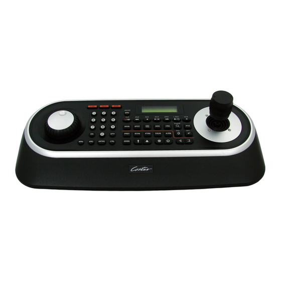
CDC2500LX
Keyboard Controller
Advertisement
Table of Contents

Summary of Contents for Costar CDC2500LX
- Page 1 CDC2500LX Keyboard Controller • Protocols include Pelco P or Pelco D, Ultrak KD6 or FrastTrax • Integrated jog shuffle for easy DVR playback control • Program and recall program preset positions from the selected dome camera • Master keyboard can be connected to up to 3 slave keyboards of the same type •...
- Page 2 WARNING AND CAUTION WARNING TO REDUCE THE RISK OF FIRE OR ELECTRIC SHOCK, DO NOT EXPOSE THIS PRODUCT TO RAIN OR MOISTURE. DO NOT INSERT ANY METALLIC OBJECTS THROUGH THE VENTILATION GRILLS OR OTHER OPENINGS ON THE EQUIPMENT. CAUTION EXPLANATION OF GRAPHICAL SYMBOLS The lightning flash with arrowhead symbol, within an equilateral triangle, is intended to alert the user to the presence of uninsulated "dangerous voltage"...
-
Page 3: Fcc Compliance Statement
FCC COMPLIANCE STATEMENT FCC INFORMATION: THIS EQUIPMENT HAS BEEN TESTED AND FOUND TO COMPLY WITH THE LIMITS FOR A CLASS A DIGITAL DEVICE, PURSUANT TO PART 15 OF THE FCC RULES. THESE LIMITS ARE DESIGNED TO PROVIDE REASONABLE PROTECTION AGAINST HARMFUL INTERFERENCE WHEN THE EQUIPMENT IS OPERATED IN A COMMERCIAL ENVIRONMENT. -
Page 4: Important Safeguards
IMPORTANT SAFEGUARDS 1. Read these instructions. 2. Keep these instructions. 3. Heed all warnings. 4. Follow all instructions. 5. Do not use this apparatus near water. 6. Clean only with dry cloth. 7. Do not block any ventilation openings. Install in accordance with the manufacturer's instructions. -
Page 5: Table Of Contents
Table of Contents Chapter 1 — Introduction ......................... 1 1.1 Features ............................1 1.2 Package Contents .......................... 2 1.3 Required Installation Tools ......................2 1.4 Connectors ............................ 2 Chapter 2 — Installation and Configuration .................... 3 2.1 Basic Configuration of Fastrax Dome System................. 3 2.2 Configuration with DVR. - Page 6 Chapter 6 — Operation ........................... 27 6.1 Keyboard Lock/Unlock (Hidden command) ................... 27 6.2 Controlling Multiplexer ........................27 6.2.1 Selecting Multiplexer ......................27 6.2.2 Dome Camera Selection ....................27 6.3 Summary of Keyboard Controls ....................28 6.3.1 Keys for Dome camera ....................... 29 6.3.2 Keys for Multiplexer ......................
-
Page 7: Chapter 1 - Introduction
Chapter 1 — Introduction 1.1 Features This keyboard controller is capable of controlling dome cameras and providing remote control functions for a variety of external switching devices such as Multiplexers, Digital Video Recorders etc. A combination of 4 Keyboard controllers and 5 Multiplexers comprises a small matrix system (64x4) using its remote control functions and programmable macro functions. -
Page 8: Package Contents
1.2 Package Contents The package contains the following. Q’ty Description Keyboard controller Instruction manual 12VDC Power supply (SMPS) Power Cord 1.3 Required Installation Tools No special tools are required to install the KBD controller. Refer to the installation manuals for the other items that make up part of your system. -
Page 9: Chapter 2 - Installation And Configuration
Chapter 2 — Installation and Configuration 2.1 Basic Configuration of Fastrax Dome System. Figure 2 – Basic installation diagram... -
Page 10: Configuration With Dvr
2.2 Configuration with DVR. Figure 3 –installation diagram with DVR... -
Page 11: Configuration With Mux
2.3 Configuration with MUX. Figure 4 –installation diagram with MUX... -
Page 12: Configuration Of Master And Slave Keyboards
2.4 Configuration of Master and Slave Keyboards. Figure 5 –Master and Slave keyboard connection Note: Connect the DOME1 port of all slave keyboards to the DOME2 port of the master keyboard and set the DIP SW 1 and 2 as the figure above. - Page 13 Without J-BOX Master Keyboard Setting Slave Keyboard Setting 1. Dip switch the of S1 is "ON"...
- Page 14 With J-BOX Master Keyboard Setting Slave Keyboard Setting 1. Dip switch the of S1 is "ON"...
-
Page 15: Termination
2.5 Termination. The first and last devices in an installation (dome and keyboard controller) must have the data line terminated by setting the DIP switch. Without proper termination, there is potential for control signal errors. Total length of the cable for communication should not exceed 4000ft (1 .2Km). Refer to Figure 6 for setting the dome camera and keyboard controller termination. -
Page 16: Dip Switch Settings
2.6 Dip Switch Settings. Termination and Master/Slave: Set the switches according to your configuration. Figure 7 – Keyboard DIP Switches SETTING DESCRIPTION DOME1 Termination DOME2 Termination J-BOX Data2 Termination Reserved DOWNLOAD ON DOWNLOAD OFF SLAVE MASTER Table 1 - S1 Switch Setting 2.7 Multiplexer Configuration Duplex setup: NOTE:... - Page 17 Set the multiplexer functions as follows: (Press the Menu key of the multiplexer to enter the Unit Options menu.) 9 Unit Options Unit Number: 001 (first Mux) or 002 (second Mux) Communication Type: RS 485 Baud rate: 9600 bps PORT: ** Protocol:** B (If you see this line, the multiplexer has the new ROM) ** The old ROM version does not show Protocol selection option.
-
Page 18: Chapter 3 - Keyboard Setup
Chapter 3 — Keyboard Setup To setup the keyboard controllers, the user needs to setup the network, passwords and perform special tasks such as Uploading and Downloading programmed data from the dome cameras. To enter the Keyboard menu, press and hold CTRL and press MENU expressed as CTRL+MENU in the manual. You will see the following menu. -
Page 19: Change Administrator Password
Change Administrator Password Current PW : XXXX NEW PW : YYYY Confirm PW : YYYY Save and Exit This screen allows you to change administrator password. Enter 4 digits password and press ENTER . Factory Default setting is 9999. Note) Factory default Administrator’s password is 9 9 9 9 + ENTR . User password is 1 1 1 1 + ENTR If you forgot your own password, contact service personnel or distributor. -
Page 20: Com Ports
Com Ports Com Ports Com Ports 1.DOME1 : DOME 1.DOME1 : DOME 2.DOME2 : NONE 2.D2/DVR : NONE 3.RS232 : NONE 3.ALARMPC: NONE Save and Exit 4.MUX/KBD: NONE 5.DVR/AUX: NONE Save and Exit < J-BOX :OFF> < J-BOX :ON> J-BOX :OFF DOME1 2400~38400 None/Dome/DVR5... - Page 21 This menu is for assignment when multiplexers are installed in two levels. Two levels means that spot outputs of the first level multiplexers is connected to the video input of the second level multiplexer. Press NO + CAM will display the selected camera on the spot output of the second level multiplexer. MUX Channel: NO(no use), 16, 28, 32, 48, 64 –...
- Page 22 MUX A MUX A MUX B MUX A MUX B Dome ID Mux 01 Cam1 Cam2 Cam3 Dome ID Mux 01 Dome ID Cam4 Mux 02 → → Cam 1 Cam1 Cam5 → Cam6 → Cam2 Cam 2 → Cam3 Cam7 →...
-
Page 23: Set Slave Kbd
Figure 8 – MUX configuration Set Slave Kbd Set Slave Kbd 1.Slave KBD : OFF 2.MUX cont : OFF 3.DVR cont : OFF 4.Dome Menu : OFF 5.Slave KBD Unit Save and Exit This screen allows you set up Slave KBD controller, how many the slave KBD controller and Mux menu controllability and DVR menu controllability, etc. -
Page 24: Time / Date
At this time, the F2E protocol could not be changed. To add the other camera: 1. Select the blank line (- - -) by moving the joystick down or up. 2. Twist the handle of the joystick clockwise, then the next camera number displays or press camera number and CAM key, if that number is not already defined, the camera number displays. -
Page 25: Lcd
check to OFF. 3.6 LCD 1.Bright 2.Backlight Save and Exit - Bright : 01~12 - Backlight : ON/OFF Data Bank 3.7 DATA BANK 1:Download-> 2:Download-> Exit(ESC) The data bank function allows you to download the programmed data from the selected camera and to upload the saved data of the keyboard to the selected camera. -
Page 26: Initialization
3.8 INITIALIZATION MAIN MENU To initialize the keyboard, select Initialization. 8.Initialization After Initialization, the keyboard returns it to the factory value. ARE YOU SURE? ENTER OR ESC 3.9 HOLD TIME MAIN MENU 9.Hold time:005s When the dome ID of the master keyboard is the same as the slave keyboard or the one from AUX IN mode(dome2 port), during the hold time after the master keyboard control the dome, the slave keyboard and the unit from the AUX IN mode(dome2 port) cannot control the dome. -
Page 27: Chapter 4 - Slave Keyboard Setup
Chapter 4 — Slave Keyboard Setup Master keyboard should be setup as following procedure. of S1 “OFF”. 1. Check for dip switch the 8 2. Press CTRL + MENU. Check Slave KBD setting “ON”. Network ▶ Set Slave KBD ▶ Slave KBD : ON Network ▶... -
Page 28: Chapter 5 - Install With Dvr Series
Chapter 5 — Install with DVR Series 5.1 Install with Standalone DVR Series When user wants to connect with DVR, proceed as the following order. Connect RS232 cable between RS-232 Port of DVR and RS232 of the Keyboard. (This connection enables DVR control remotely from KBD controller) How to setup the KBD controller. - Page 29 Select “System Information” on the system menu and change UNIT ID. C. Select “Camera” on the Device menu. Unit ID should be 1 up to 99. Unit ID is not allowed number “0”. D. Set “PTZ Device” and “ID” of the dome camera. Select RS232/RS485 after PTZ is installed, and then set-up as below table.
-
Page 30: Install With Pc Dvr Series
After setting Unit ID, Camera, and RS232/RS485, installing dome camera is basically completed. Please refer to the manual of DVR for the other installation. Press the related number of the controller which is correspondent to unit ID of DVR. Then press DVR button and adjust unit ID of the controller Make sure if any change is appeared on screen when you press button of the controllerfor... - Page 31 4. How to setup PC DVR Switch the PC DVR on. If press setup button on the above screen, the below screen will be appeared. Select camera input number that dome camera connected. Then install as below to select set-up PTZ after checking PTZ box. Port : COM1 RX Device : Fastrax….
- Page 32 5. How to PC DVR Remote setup If selects Setup on main menu, the below screen will be appeared. B. After selecting System and checking Remote control box, please install as below to select Setup remote control. Device ID is not allowed number “0”. Port : COM2 Baud Rate : 9600...
-
Page 33: Chapter 6 - Operation
Chapter 6 — Operation 6.1 Keyboard Lock/Unlock (Hidden command) When the user leaves the control desk, he may wish to lock the keyboard controller to prevent unauthorized use. Pressing 7 7 7 + ENTER will lock the keyboard controller. Pressing 7 7 7 + ENTER while the keyboard is locked will open the password screen. -
Page 34: Summary Of Keyboard Controls
Pressing SPOT No. + SPOT + Camera No. + ENTER will switch the selected camera number to the specific spot monitor output of the multiplexer. The selected camera can be a dome camera or a standard camera. The Keyboard controller maintains control of the previously selected dome camera. It does not change the main output of the multiplexer. -
Page 35: Keys For Dome Camera
6.3.1 Keys for Dome camera Function Key Label Descriptions Displays the selected camera on the spot out of the multiplexer and allows the camera to be controlled by the keyboard controller, if the selected camera is a Camera dome camera. No. -
Page 36: Keys For Multiplexer
6.3.2 Keys for Multiplexer Function Key Label Descriptions Select Mux Select Multiplexer (e.g.; 1 or 2 + MUX) Puts the multiplexer in Full-Screen Mode of the selected camera Full Screen No. + Picture-in-Picture mode. 2 by 2 Displays view of four cameras. The remaining cameras can be Display sequenced in the lower-right window. -
Page 37: Keys For Dvr [Dvr1-4, Pc-Dvr]
6.3.3.1 Keys for DVR [DVR1-4, PC-DVR] Function Key Label Descriptions Id Selection DVR ID Selection. (e.g.:1 or 2 + DVR). Enter the Quick Setup screen. You will need to enter the MENU administrator password to access the Quick Setup. Pressing the MACRO button also closes the current menu or setup dialog box. - Page 38 Function Key Label Descriptions First, it will reset the DVR’s outputs including the internal buzzer during Alarm an alarm. Second, it will display the event log when you are in the live monitoring mode unless there is an active alarm. [DVR1- 4]Select a highlighted item or completes an entry that you Enter have made.
-
Page 39: Example Of Key Operation In Pc-Dvr
6.3.3.2 Example of Key operation in PC-DVR Function Key Label Live(Guard) Mode Playback Mode MENU NO ACTION MACRO Record Record ON / OFF Recall Preset Recall Preset No. + Search Go to Playback mode Stop Rewind NO ACTION Rewind one image X times Fast rewind NO ACTION... -
Page 40: Dvr5 Protocol For The Dvr For The Version 3.1.0 And Over
6.4 DVR5 protocol for the DVR for the version 3.1.0 and over Installation of the DVR5 protocol when one DVR is used. Note: When you set the protocol to DVR5, the keyboard operates as the DVR’s keyboard only and you must install domes to the DVR only. RS232 When you control the PTZ camera by the DVR, follow as below. - Page 41 4. How to setup DVR: D. Switch the DVR on. E. Enter the Menu according to the DVR’s instruction manual. F. Change the Port to “RS232” of the remote control in the devices menu. G. Confirm matching the setup of RS232 with the keyboard. Ex: Baud Rate:9600,Data Bit:8,Stop Bit:1, Parity:None) H.
- Page 42 Installation of DVR5 protocol when many DVR use. RS232 TO RS485 CONVERTER RS232 TO RS485 CONVERTER When you control PTZ cameras on many DVRs, you need RS232 to RS485 converter. PTZ cameras are connected to RS232 to RS485 converter by the RS232 port of the DVR and the keyboard is connected through the RS485 port of the DVR.
- Page 43 Keys for Dome camera: Key Label Descriptions Camera 1..16 + CAM Displays the selected camera number. selection Cancels current inputs. Cancel Exits from currently running functions or menu, error status, etc. Alarm ALRM No Action Immediately calls Home function. HOME Home Deletes selected value or function in programming mode Pressing Prst will bring up the preset programming menu.
- Page 44 *See the DVR’s manual to know in detail. Keys for DVR[DVR5] Key Label Descriptions DVR ID Selection. (e.g.:1 or 2 + DVR). DVR Selection Open a Pan/Tilt/Zoom screen which allows you to control properly configured cameras. Play/Pause Play recorded data / Pause playing. Play video backward at high speed.
-
Page 45: Appendix A- Short Cut Key
Appendix A- Short Cut Key Short Cut Key Function Pop up preset setup menu. PRST TOUR Pop up Tour setup menu. PTRN Pop up Pattern setup menu. SCAN Pop up Auto Scan setup menu. NO.+PGM +PRST Store the current view at the selected number. Short Cut Key Function Short Cut Key... - Page 46 Short Cut Key Function Short Cut Key Function 150 + ON Image Flip ON 150 + OFF Image Flip off 151 + ON Origin Check 152 + ON Place the camera in the 0° area horizontally. Go to the normal speed 153 + ON Go to the slow speed mode 153 + OFF...
-
Page 47: Appendix B- Trouble Shooting
Appendix B- Trouble Shooting If problems occur, verify the installation of the camera with the instructions in this manual and with other operating equipment. Isolate the problem to the specific piece of equipment in the system and refer to the equipment manual for further information. -
Page 48: Appendix D -Specification
Appendix D -SPECIFICATION GENERAL Certification CE EMC, FCC CLASS A ELECTRICAL 16 X 2 Line LCD Joystick Zoom handle Joystick Input Voltage 12 VDC Power Consumption Communications RS-485/232 baud rate: 2400 ~38400 bps (default:9600bps) Dome1 Port (RS-485) Up to 127 dome cameras including 32 Alarm mode on. Up to 127 dome cameras including 32 Alarm mode on / Dome2 Port (RS-485) SLAVE KEYBOARD / DVR/MULTIPLEXER... - Page 49 MEMO...
- Page 51 Keyboard Controller I n s t r u c t i o n M A N U A L 50302196D PRINTED IN KOREA...
Need help?
Do you have a question about the CDC2500LX and is the answer not in the manual?
Questions and answers