Table of Contents
Advertisement
Advertisement
Table of Contents

Summary of Contents for Master Therm BoxAir
- Page 1 HEA T PUMPS HEAT PUMPS INSTALLATION AND OPERATING MANUAL BoxAir BoxAir Inverter EasyMaster EasyMaster IndoorSplit AirMaster aku AirMaster mini AquaMaster AquaMaster Inverter AquaMaster Inverter Combi DirectMaster Czech Product Catalog: AM, AQ, EM, BA Documentation: IOM Edition: 28/07/2014 tiché...
-
Page 2: Table Of Contents
Positioning, with Regard to Air Flow and the Condensate Drain ........10 1.4.2 Positioning, with regard to noise..................10 1.4.3 Mechanical installation ....................15 1.4.4 Mechanical installation, BoxAir units................17 Piping Connection of Indoor and Outdoor Units – AM, EM..............18 Danger ............................18 Piping............................18 2.2.1 Mounting the Piping......................19 2.2.2... - Page 3 Single loop heating system....................46 5.6.2 BoxAir and BoxAir Inverter multi-circuit system with DHW..........47 5.6.3 BoxAir / BoxAir Inverter multi-circuits, charging pump DHW ..........48 5.6.4 Heating system charge for BoxAir and BoxAir Inverter ............48 5.6.5 Venting the system for BoxAir a BoxAir Inverter ..............48 ASW units connection ......................49...
- Page 4 AM, EM, AQ, BA, ASW - IOM Commissioning ..........................60 Mechanical Installation Inspection...................60 Piping Network Inspection.......................60 Electrical wiring check......................60 Start-up and Filling of Start-up Protocol...................60 Maintenance ...........................61 Introduction ..........................61 Personnel Qualification ......................61 Quarterly Maintenance......................61 Annual Maintenance .......................61 Warranty ..........................62 Legislation ..........................62 Revision history ..........................62 page: 4/64 Ing.Jiří...
-
Page 5: Installation And Location Of The Unit
AM, EM, AQ, BA, ASW - IOM 1 Installation and location of the unit The equipment must be installed and commissioned by an authorized, specialized installation company. The installation must comply with this installation manual and national regulations. 1.1 Unit delivery Check the unit for possible damage or missing parts. - Page 6 AM, EM, AQ, BA, ASW - IOM Clearances: AquaMaster, EasyMaster, AirMaster MINI AquaMaster x.2, AirMaster x.2 page: 6/64 Ing.Jiří Jiránek...
- Page 7 AM, EM, AQ, BA, ASW - IOM Spiro tube 400mm +25mm PUR inlet grille PMR-400W SONOFLEX 406mm pipe draining 40mm flexi outlet grille/ gravity valve PMR-400W (PER-400W) fan motor access panel access panel - electric - fan propeller Clearances and installation: 1OEM26-45VK (evaporator - indoor split) page: 7/64 Ing.Jiří...
- Page 8 AM, EM, AQ, BA, ASW - IOM Spiro tube 400mm +25mm PUR inlet grille PMR-400W SONOFLEX 406mm tube access panel electric access panel XPS 40mm outlet grille / gravity valve PMR-400W (PER-400W) compressor access panel Clearances and installation: ASW page: 8/64 Ing.Jiří...
-
Page 9: Mechanical Installation
AM, EM, AQ, BA, ASW - IOM 1.3.2 Mechanical installation The inner unit of the Heat Pump should be located in a detached room – a machinery room. In the case the room is next to protected areas (bedroom, children rooms etc.), the wall between must be made as sound-proof, minimum sound reduction of 30dBA. -
Page 10: Positioning Of The Outdoor Unit
AM, EM, AQ, BA, ASW - IOM Warning: Please keep in mind that not respecting the minimum room volume can in the case of coolant leakage result in injury or even death. Always respect actual national directives regarding installation of cooling equipment (for EU EN378). Underground unventilated rooms are extra hazardous because the coolant always stays near the ground. - Page 11 AM, EM, AQ, BA, ASW - IOM Two reflecting walls: d<3m, FU=+6dBA Between reflecting walls: FU=+6dBA page: 11/64 Ing.Jiří Jiránek...
- Page 12 AM, EM, AQ, BA, ASW - IOM Barrier attenuation factor: INSTALLATION ON A FLAT ROOF WITH DAMPENING WALL EVALUATION POINT EVALUATION POINT BUILDING CORNER AS A NOISE BARRIER EVALUATION POINT EVALUATION POINT BARRIER NOISE SOURCE – Distance between the noise source and evaluation point around a barrier –...
- Page 13 If this estimate approximates the noise level limit, you should consider the necessity of additional measures. MASTER THERM CZ IS NOT LIABLE FOR ANY DIFFERENCES BETWEEN THE RESULTS OBTAINED WITH THE USE OF THIS METHOD AND THE INSTALLED REALITY page: 13/64 Ing.Jiří...
- Page 14 AM, EM, AQ, BA, ASW - IOM Layout drawing for the noise evaluation: page: 14/64 Ing.Jiří Jiránek...
-
Page 15: Mechanical Installation
AM, EM, AQ, BA, ASW - IOM 1.4.3 Mechanical installation There are 3 different variants of the outer units. A vertical one with a bracket on the wall, a vertical one on legs, and a horizontal one on legs. For types with legs a special base must be built. - Page 16 AM, EM, AQ, BA, ASW - IOM EM60Z / EM75Z outdoor unit: 4 legs are delivered with the outdoor unit for location on a suitable basement. Recommended basement is on picture below. wall plastic tube concrete 100-150mm like casing terrain draining acc.
-
Page 17: Mechanical Installation, Boxair Units
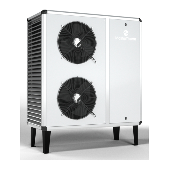
AM, EM, AQ, BA, ASW - IOM 1.4.4 Mechanical installation, BoxAir units BoxAir packaged air source heat pumps are dedicated for outdoor installation. Operating range is -20÷+30˚C. Because of outdoor installation, power supply requires additional protection, like RCD circuit breaker or additional earth wiring. Minimum free area around unit is neccessary for sufficient air flow, heating water piping and electrical connection. -
Page 18: Piping Connection Of Indoor And Outdoor Units - Am, Em
AM, EM, AQ, BA, ASW - IOM 2 Piping Connection of Indoor and Outdoor Units – AM, EM After mechanical installation of split heat pumps AM and EM, installation of piping connection between the indoor and outdoor unit must be performed.. 2.1 Danger The inner units of heat pumps are filled with coolant r407c or r410a by the manufacturer. -
Page 19: Mounting The Piping
AM, EM, AQ, BA, ASW - IOM 2.2.1 Mounting the Piping The piping must be mounted to a firm base (wall etc.) using special brackets. Recommended pitch between brackets is 1 to 2m to prevent vibrations of the piping during operation. The piping must not be in contact with the base. -
Page 20: Liquid Line
AM, EM, AQ, BA, ASW - IOM 2.2.4 Liquid line There are no special requirements for liquid piping. 2.3 Welding Only hard oxygen-propane or oxygen-acetylene flame welding can be employed. Welding material to be used is solder with minimum content of silver 5% (L-Ag5P). The welding is performed with inner protection atmosphere of nitrogen (N2). -
Page 21: Units Mini With In-Built Liquid Receiver
AM, EM, AQ, BA, ASW - IOM 2.5.1 Units MINI with In-built Liquid Receiver Units equipped with the liquid receiver have installed the “ROTALOCK” valve. This valve is located on the upper part of the liquid receiver and it is closed as default. Check that it is closed prior to the vacuuming and then open the ball valve of the liquid line (small valve). -
Page 22: Earth Exchanger For Direct Evaporating- Aqxxd
AM, EM, AQ, BA, ASW - IOM liquid line vapour line heat pump box insulation down inside the cabinet Performance and completion of heat insulation 3 Earth Exchanger for Direct Evaporating– AQxxD The same instructions as in the previous chapter apply for completion of the earth exchanger and piping positioning. -
Page 23: Distributor And Collector For Aq9Z1D
AM, EM, AQ, BA, ASW - IOM 3.2.2 Distributor and Collector for AQ9Z1D 2 pieces of standard T fitting are used for distribution and collection of 2 refrigerant lines. Vertical inlet orientation is required for refrigerant distribution (vapor and liquid mixture). If elbow is used in front of the distributor, it must be oriented perpendicularly to the loop lines. -
Page 24: Liquid And Vapor Lines
AM, EM, AQ, BA, ASW - IOM 3.2.3 Liquid and Vapor Lines After connecting the circuits using the distributor and collector, the Heat Pump is connected using the liquid and vapour piping. Diameter and maximum length is in the following table. HP type D Vapour d Liquid... -
Page 25: Ground Loop And Heat Pump Interconnection
AM, EM, AQ, BA, ASW - IOM 3.2.5 Ground Loop and Heat Pump Interconnection The distributor and collector are usually installed in the collecting shaft which is made of shaft rings of appropriate diameter, usually 80cm. It is also recommended to use plastic prefabricated shafts. -
Page 26: Ground Loop For Aq Units
AM, EM, AQ, BA, ASW - IOM 4 Ground Loop for AQ units 4.1 System Description This natural resource exploits accumulated solar energy. During the summer the earth surface is warmed by solar energy. In winter we withdraw this energy and using the heat pump we use it for heating. - Page 27 AM, EM, AQ, BA, ASW - IOM The following table lists recommended configurations of standard horizontal collectors: dry soil 70m H.Cap. Soil Pipe Circuit Pipe 200m 300m Spacing HP Type B0W35 Area Length Volume Dimension Loops Loops [kW] AQ17 PE25 1200 AQ22(AQ22I) PE25...
-
Page 28: Slinky H Horizontal Loop
AM, EM, AQ, BA, ASW - IOM 4.2.2 SLINKY H Horizontal Loop This collector is based on a principle of building a large heat transfer area, which allows for absorbing heat to a distance of up to 2,5m from the center of the piping system. This system has lower costs for excavation works, but it is necessary to use more piping and thus the total volume of anti-freeze mixture is increased. -
Page 29: Vertical Ground Loop
AM, EM, AQ, BA, ASW - IOM The following table lists recommended configurations of SLINKY collectors: dry soil 70m /kW – use is not recommended SLINKY - wet soil 40m2/kW H.Cap. Soil Pipe Circuit Pipe 200m HP Type B0W35 Area Length Volume Dimension... - Page 30 AM, EM, AQ, BA, ASW - IOM Hydrogeological survey must be carried out before the drill hole is made. The survey shall determine the subsoil and its heating properties. The drill holes are carried out by specialized drilling companies. A certified prefabricated pipe probe must be used for the drill hole armature. piping 4xPE32, or 2xPE40 heated building bentonite...
-
Page 31: Caution
AM, EM, AQ, BA, ASW - IOM Drill holes - Clay, Slate 13m/kW No of Drills H.Cap. Total Depth Pipe Circuit Pipe HP Type B0W35 Depth Loop type 1 Drill Length Volume Dimension [kW] AQ17 PE32 AQ22(AQ22I) PE25 AQ26 10,1 PE32 AQ30(AQ30I) 11,4... -
Page 32: Manifolds
AM, EM, AQ, BA, ASW - IOM 4.5 Manifolds The distributor and collector connect single loops of the ground loop heat exchanger. Its proper design is important for filling and venting the piping system. We recommend using professional prefabricated distributors. venting valve manifold body filling valve... -
Page 33: Manifolds And Heat Pump Connection
AM, EM, AQ, BA, ASW - IOM 4.7 Manifolds and Heat Pump Connection The connection can be made using plastic PE piping, or Cu piping of sufficient dimension. The following table lists maximum piping lengths depending on connection dimension for various heat pumps: maximum pipe length (both directions) [m] capacity... -
Page 34: Piping Connection !!! Use 2 Spanners
AM, EM, AQ, BA, ASW - IOM !!! use 2 spanners !!! 4.9 Piping Connection The piping must be connected to the heat pump outlets using connection screwed fittings. We recommend using fittings with cone contact area and an O-ring. Never connect the screwed fitting with cap nut and front contact area directly to the fitting of the heat pump outlet, always use proper screwed fitting which is usually a part of the screwed fitting set. -
Page 35: Anti-Freeze Mixture
AM, EM, AQ, BA, ASW - IOM 4.12 Anti-Freeze Mixture Mixtures based on Ethyleneglycol, Propyleneglycol or Ethanol can be used as anti-freeze mixture. Special mixture for heat pumps must be used. The mixture must be mixed for freezing point of at least -15°C. The correct concentration is to be found in the concentrate manufacturer documentation. -
Page 36: Connestion To The Heating System
AM, EM, AQ, BA, ASW - IOM 5 Connestion to the Heating System The heat pump must be connected to a suitable, low-temperature heating system. From the perspective of optimum efficiency the floor heating is ideal, then the wall heating, and the least convenient are radiators dimensioned to temperature gradient, typically of 50/40°C, maximum 55/45°C. -
Page 37: Connection Of Heat Pumps "Aku" - Am
AM, EM, AQ, BA, ASW - IOM 5.3 Connection of Heat Pumps “AKU” – AM The AKU heat pumps have the accumulation vessel of the heating system already installed. Their connection is thus easy and fast. The AKU unit must be connected as per the following scheme: electrical supplementary hot water heater safety valve DN25/1.8bar pump loop... -
Page 38: Connection Of Aq Heat Pumps
AM, EM, AQ, BA, ASW - IOM 5.4 Connection of AQ Heat Pumps These are units of the “MINI” type which is not equipped with an accumulation vessel. 5.4.1 AQ Single-circuit Heating System Typical usage is for floor heating, except for “dry system of floor heating”. In this method of direct connection of the heat pump to the heating system, maximally 30% of the heating system can be equipped by local regulation. -
Page 39: Aq Multi-Circuit Heating System - Switchable Heating Of Dhw
AM, EM, AQ, BA, ASW - IOM 5.4.2 AQ Multi-circuit Heating System – Switchable Heating of DHW Universal scheme for multi-circuit heating systems with accumulation vessel. Local regulation can be applied here for 100% of heating output. The volume of the accumulation vessel is determined for 15 l/kW of heating output of the heat pump for B0W35. -
Page 40: Aq Multi-Circuit Heating System - Dhw Heating Using Charge Pump
AM, EM, AQ, BA, ASW - IOM 5.4.3 AQ Multi-circuit Heating System – DHW Heating Using Charge Pump Universal scheme for multi-circuit heating systems with accumulation vessel. Local regulation can be applied here for 100% of heating output. The volume of the accumulation vessel is determined for 15 l/kW of heating output of the heat pump for B0W35. -
Page 41: Aqxxic (Combi) Units Recommended Connection
AM, EM, AQ, BA, ASW - IOM 5.4.4 AQxxIC (combi) units recommended connection Typical usage is for floor heating, except for “dry system of floor heating”. In this method of direct connection of the heat pump to the heating system, maximally 30% of the heating system can be equipped by local regulation. -
Page 42: Connection Of Am Mini, Em Heat Pumps
AM, EM, AQ, BA, ASW - IOM 5.5 Connection of AM MINI, EM Heat Pumps These are “MINI” type units which do not have the accumulation vessel. 5.5.1 Heating System with Pump Circuits and Through-flow Pre-heating of DHW This is the simplest connection of the air/water heat pump machinery room, which is suitable especially for reconstructions. -
Page 43: Am Mini, Em Single-Circuit Heating System
AM, EM, AQ, BA, ASW - IOM 5.5.2 AM MINI, EM Single-circuit Heating System Typical usage is for floor heating, except for “dry system of floor heating”. This connection is not suitable for radiators. In this method of direct connection of the heat pump to the heating system, maximally 30% of the heating system can be equipped by local regulation. -
Page 44: Am Mini, Em Multi-Circuit Heating System - Switchable Heating Of Dhw
AM, EM, AQ, BA, ASW - IOM 5.5.3 AM MINI, EM Multi-circuit Heating System - Switchable Heating of DHW Universal scheme for multi-circuit heating systems with accumulation vessel. Local regulation can be applied here for 100% of heating output. The volume of the accumulation vessel is determined for 15 l/kW of heating output of the heat pump for A7W35. -
Page 45: Am Mini / Em Multi-Circuit Heating System - Dhw Heating Using Charge Pump
AM, EM, AQ, BA, ASW - IOM 5.5.4 AM MINI / EM Multi-circuit Heating System - DHW Heating Using Charge Pump Universal scheme for multi-circuit heating systems with accumulation vessel. Local regulation can be applied here for 100% of heating output. The volume of the accumulation vessel is determined for 15 l/kW of heating output of the heat pump for A7W35. -
Page 46: Boxair And Boxair Inverter System Connection
AM, EM, AQ, BA, ASW - IOM 5.6 BoxAir and BoxAir Inverter system connection BoxAir heat pumps are dedicated for outdoor installation. Heating system piping has outdoor installation, therefore antifreeze must be used for heating system filling. 5.6.1 Single loop heating system Typical usage is for floor heating, except for “dry system of floor heating”. -
Page 47: Boxair And Boxair Inverter Multi-Circuit System With Dhw
HC expansion vessel tank in tank DHW vessel heating system buffer with integrated manifold * it could be used for towel radiators BoxAir / BoxAir Inverter machinery room for multiplecircuits and DHW page: 47/64 Ing.Jiří Jiránek... -
Page 48: Boxair / Boxair Inverter Multi-Circuits, Charging Pump Dhw
DHW tank with heat exchanger BoxAir / BoxAir Inverter machinery room for multiple circuits and charging DHW 5.6.4 Heating system charge for BoxAir and BoxAir Inverter Antifreeze mixture of propylene glycol with freezing point -20°C is required, due to outdoor installation. -
Page 49: Asw Units Connection
AM, EM, AQ, BA, ASW - IOM 5.7 ASW units connection These units are not equipped with pump nor the auxiliary heater. ASW units are didicated for connection to the DHW tank and heating system buffer. Controller is not designed for heating circuits control. -
Page 50: Heating Circuits
AM, EM, AQ, BA, ASW - IOM 5.8 Heating Circuits There are two types of heating circuits: pump and mixing. They must be carefully designed and installed, especially in the case of using more heating circuits. 5.8.1 Manifolds This is a piping element designed in such way that the individual heating circuits affect each other as little as possible. -
Page 51: Pump Heating Circuits
AM, EM, AQ, BA, ASW - IOM 5.8.2 Pump heating circuits Usually they are used for radiators, heating pools, etc. The following image describes the components of a typical pump circuit which are required for flawless operation and maintenance. return line from heating circuit heating circuit inlet connection fitting check valve... -
Page 52: Preparation Of Domestic Hot Water (Dhw)
/10kW of heating output of the heat pump. Therefore the usage is limited for commonly available types of exchangers. For heat pumps AM, EM, BoxAir a BoxAir Inverter deactivation of DHW in defrost mode must be activated in heat pump controller. -
Page 53: Charging Pump For Tank With Heat Exchanger
AM, EM, AQ, BA, ASW - IOM heating system inlet/outlet tap water inlet / DHW outlet 3 way valve indirect DHW tank heat exchanger 2-3m /10kW ! 5.9.3 Charging pump for tank with heat exchanger Universal scheme usable for all types of heat pumps. The Charge Pump draws heating water from accumulation boiler of the heating system and heats DHW. -
Page 54: Preheating In Accumulation Vessel Of The Heating System And Electric Afterheating
AM, EM, AQ, BA, ASW - IOM 5.9.4 Preheating in Accumulation Vessel of the Heating System and Electric Afterheating This scheme is also universally usable for all heat pumps. It is especially suitable for reconstructions with pre-installed electric or gas heater of DHW. It is not suitable for high demand of DHW. -
Page 55: Piping Connection !!! Use 2 Spanners
AM, EM, AQ, BA, ASW - IOM !!! use 2 spanners !!! 5.10 Piping Connection The piping must be connected to the heat pump outlets using connection screwed fittings. We recommend using fittings with cone contact area and an O-ring. Never connect the screwed fitting with cap nut and front contact area directly to the fitting of the heat pump outlet, always use proper screwed fitting which is usually a part of the screwed fitting set. -
Page 56: Electric Power Connection
AM, EM, AQ, BA, ASW - IOM 6 Electric Power Connection Při provádění elektroinstalace vždy nahlédněte do elektrického schematu zapojení, které je součástí dodávky tepelného čerpadla. 6.1 Hlavní napájení Heat pumps are always provided with a main switch and current zero and grounding terminal. Connect the power supply cable to the main switch connectors and current zero and grounding terminal. -
Page 57: Tariff Signal, Remote On/Off Signal
AM, EM, AQ, BA, ASW - IOM heat pump type no aux. heater aux. heater (kW) 3x400V 2x4,5 2x7,5 EM26Z 13A“C“ 20A“B“ 20A“B“ 25A“B“ EM30Z 13A“C“ 20A“B“ 20A“B“ 25A“B“ EM37Z 16A“C“ 20A“B“ 25A“B“ 25A“B“ EM45Z 16A“C“ 25A“B“ 25A“B“ 25A“B“ EM60Z 25A“C“... -
Page 58: External Components (Pumps, Valves)
AM, EM, AQ, BA, ASW - IOM 6.4 External components (pumps, valves) Use wiring diagram supplied to connect external components. If expansion card is used, use. X3 terminals. Temperature probes connect directly to expansion card terminals J9 a J10. 7 Control and measurement Heat pumps are equipped for control of different systems. -
Page 59: Mixing Valves Servo
AM, EM, AQ, BA, ASW - IOM 7.4 Mixing valves servo Mixing valves are wired to heat pump terminals or X3 terminals in case of expansion card. Only servos with 0-10V control signal and 24VAC power supply must be used. Power supply is directly available from terminals. -
Page 60: Commissioning
AM, EM, AQ, BA, ASW - IOM 8 Commissioning The heat pump controller must be configured for the heating system before the commissioning. The description of the control system and the manual for its setting is in a separate document supplied with the heat pump. -
Page 61: Maintenance
All work on inner components of the unit can be performed when it is turned off, the main switch in position “0”. The Investor can choose any servicing organization approved by Master Therm company. 9.3 Quarterly Maintenance This maintenance does not require special skills, is performed by the user. -
Page 62: Warranty
Building permit is usually required for installation of the heat pump. The Master Therm company is not liable for proper operation of the equipment in the case directions and recommendations from this manual are not respected. - Page 63 AM, EM, AQ, BA, ASW - IOM NOTES: page: 63/64 Ing.Jiří Jiránek...
- Page 64 HEA T PUMPS Showroom and mailing address: Master Therm tepelná čerpadla s.r.o. Okrajová 187,253 01 Chýně Czech Republic Tel.: +420 311 516 567, Zelená linka: 800 444 000 info@mastertherm.cz, www.mastertherm.cz Head office and billing address: Master Therm tepelná čerpadla s.r.o.
Need help?
Do you have a question about the BoxAir and is the answer not in the manual?
Questions and answers