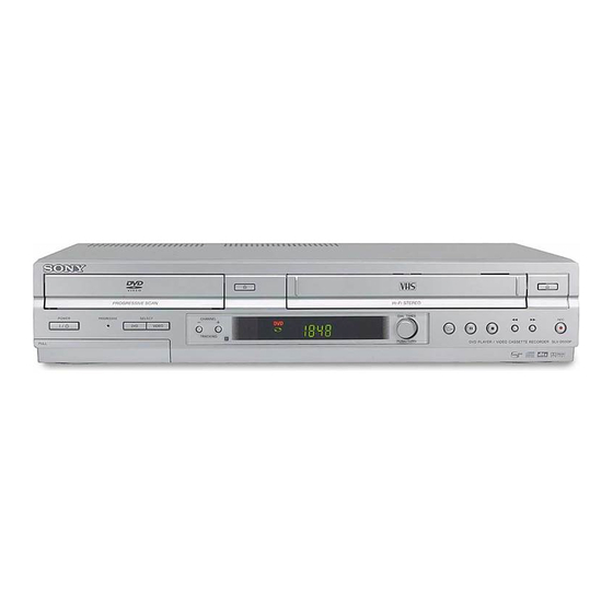
Sony SLV-D350P Service Manual
Dvd player/
video cassette recorder
Hide thumbs
Also See for SLV-D350P:
- Service manual (121 pages) ,
- Specifications (2 pages) ,
- Operating instructions manual (129 pages)
Table of Contents
Advertisement
Quick Links
SERVICE MANUAL
System
Laser
Semiconductor laser
Format
VHS NTSC standard
Video recording system
Rotary head helical scanning FM system
Video heads
Double azimuth four heads
Video signal
NTSC color, EIA standards
Tape speed
3
SP: 33.35 mm/s (1
inches/s)
8
EP: 11.12 mm/s (
7
inches/s)
16
11
LP: 16.67 mm/s (
inches/s),
16
playback only
Maximum recording/playback time
8 hrs. in EP mode (with T-160 tape)
Rewind time
Approx. 1 min (with T-120 tape)
SLV-D350P/D550P
Photo: SLV-D550P
RMT-V501D
SPECIFICATIONS
Tuner section
Channel coverage
VHF 2 to 13
UHF 14 to 69
CATV A-8 to A-1, A to W, W+1 to W+84
Antenna
75-ohm antenna terminal for VHF/UHF
Inputs and outputs
LINE IN 1 and LINE-2 IN
VIDEO IN, phono jack (1 each)
Input signal: 1 Vp-p, 75 ohms, unbalanced, sync
negative
AUDIO IN, phono jacks (2 each)
Input level: 327 mVrms
Input impedance: more than 47 kilohms
LINE OUT
VIDEO OUT, phono jack (1)
Output signal: 1 Vp-p, 75 ohms, unbalanced, sync
negative
AUDIO OUT, phono jacks (2)
Standard output: 327 mVrms
Load impedance: 47 kilohms
Output impedance: less than 10 kilohms
Refer to the SERVICE MANUAL of VHS MECHANI-
CAL ADJUSTMENT MANUAL VII for MECHANICAL
ADJUSTMENTS. (9-921-790-11)
DIGITAL OUT
OPTICAL, Optical output jack
-18 dBm (wave length: 660 nm)
COAXIAL, phono jack
Output signal: 0.5 Vp-p, 75 ohms
COMPONENT VIDEO OUT (Y, Pb, Pr)
Phono jack
Y: 1.0 Vp-p/Pb, Pr: 0.7 Vp-p, 75 ohms
S-VIDEO OUT
4-pin, mini-DIN jack
Y: 1.0 Vp-p, unbalanced, sync negative
C: 0.286 Vp-p, load impedance 75 ohms
Timer section
Clock
Quartz locked
Timer indication
12-hour cycle
Timer setting
8 programs (max.)
General
Power requirements
120 V AC, 60 Hz
VIDEO CASSETTE RECORDER
RMT-V501C/V501D
US Model
TS-10 MECHANISM
Power consumption
25 W
Power back-up
Back-up duration: 0 min
Operating temperature
0°C to 45°C (32°F to 113°F)
Storage temperature
-20°C to 60°C (-4°F to 140°F)
Operating humidity
25% to 80%
Dimensions including projecting parts and controls
(w/h/d)
×
×
Approx. 430
85
287 mm
×
×
(Approx. 17
3.4
11.5 inches)
Mass
Approx. 3.6 kg (Approx. 7.9 lbs)
Supplied accessories
Remote commander (1)
Size AA (R6) batteries (2)
75-ohm coaxial cable with F-type connectors (1)
×
×
3 y pinplug
Audio/video cord (pinplug
3) (1)
Design and specifications are subject to change without
notice.
ENERGY STAR
¤
is a U.S. registered mark.
¤
As an ENERGY STAR
Partner, Sony Corporation has
determined that this product meets the ENERGY STAR
guidelines for energy efficiency.
DVD PLAYER/
¤
Advertisement
Table of Contents


Need help?
Do you have a question about the SLV-D350P and is the answer not in the manual?
Questions and answers