Table of Contents
Advertisement
Quick Links
Wingspan:
Wing Area:
Weight:
Radio:
Engine:
The M1A1 Flying Tank is fun and easy to build. We have done all the hard work for you. It can easi-
ly be framed up and covered in a weekend. While it may look a little bit different, the construction
techniques used are the same as most other airplanes. The average modeler will have no problem. You
will find top quality Laser Cut balsa, plastic and plywood, as well as beautiful CNC Cut foam cores
and parts! It is the ultimate high tech kit!
Low speed flying is great, with huge elevons and tons of surface area, it will crawl along with
full control and amazing stability. To speed up all you need to do is give it gas! It flies smooth, sta-
ble, and responds great. Most say that it flies like a low wing sport plane. Landings are breeze, just
lower the throttle and she'll settle in on her own. All in all you can't find a plane that gets you more
attention and is as fun to fly.
Copyright © 2010
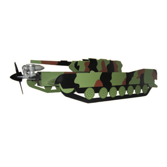
M1A1 Flying Tank
A Sport Scale Flying Military Tank
Specifications
24"
864 sq in
7 lbs.
4 Channel w/ Elevon Mixing
.46 - .61 two-stroke / .53 - .71 four-stroke
Kit# FTZ3015
Advertisement
Table of Contents

Related Manuals for FlyingThingZ M1A1 Flying Tank

Summary of Contents for FlyingThingZ M1A1 Flying Tank
- Page 1 .46 - .61 two-stroke / .53 - .71 four-stroke The M1A1 Flying Tank is fun and easy to build. We have done all the hard work for you. It can easi- ly be framed up and covered in a weekend. While it may look a little bit different, the construction techniques used are the same as most other airplanes.
-
Page 2: Table Of Contents
Table of Contents Warranty Information................. 3 Warnings and Safety Precautions. -
Page 3: Warranty Information
Further, FlyingThingZ, Inc. reserves the right to modify this warranty without prior notice. In that FlyingThingZ, Inc. has no control over the final stages of assembly or material used for the final assembly, no liability shall be assumed nor accepted for any damage of the final user-assembled product. By the act of using the final product, the user accepts all resulting liability. -
Page 4: Using This Manual
Using This Manual This manual is divided into sections to aid in the assembly process. It provides an easier more concise layout allowing for breaks between each major section. Additionally, check boxes have been provided next to each step to help keep track of the completed assembly process. -
Page 5: Additional Requirements
Nose Gear Hardware #2 x 9/16 Wood Screws 5/32” Wheel Collars Additional Kit Requirements 3 2.5” to 3” Wheels FlyingThingZ Pre-cut Self Adhesive Vinyl Covering Motor Mount and Mounting Hardware Clear Packing Tape 2’ Medium Fuel Tubing 4 2-56 Pushrods Prop Suited to Engine 8oz. -
Page 6: Fuselage Assembly
A. Fuselage Assembly A3. Glue the two ply firewall pieces utilizing clothe pins to hold the parts together. Verify the orientation of the holes on the firewall as they will play a vital role later on. A1. Start by lining up the two fuselage sides and the two ply fuselage reinforcements. - Page 7 A10. Size and cut a hatch tongue plate and glue it to the notch- es on the back of the fuselage. Sand the edges flush with the sides of the fuselage. Sand the rearward part of the hatch tongue plate to match the angle of the fuselage as shown in the image above.
- Page 8 A13. Line up a piece of 1/4 x 1/4 balsa stick against the fuse- lage cross brace. Scribe a line where the balsa stick lines up with A17. Reinstall the fuselage hatch and flip the fuselage around the hatch bolt plate. Cut the balsa stick along the line. so that the bottom is facing up.
- Page 9 A25. Flip the fuselage over and do the same on the other side. In the image above, you can see the cutout on the fuselage/wing saddle mentioned in step A24. A20. Cut several pieces of the 1/16” balsa sheet. For added strength make your cuts are against the grain.
-
Page 10: Preparing The Foam
B. Preparing the Foam B1. Sand the foam using #120 grit sand paper on a sanding block. The foam should have a smooth texture after sanding is completed. Be extremely careful not to distort the foam in any way. Sand edges and curves very lightly. Enough pressure should be applied to smooth out the foam, not to change its shape. - Page 11 C6. Reinsert the cut foam center piece along the fuselage back plate. If there is any excess overhang on the trailing edge, make a C9. Using a rotary tool with a router attachment cut the foam mark and cut the excess until the back is flush with the trailing inside your line marks.
-
Page 12: Elevon Assembly
Repeat for the other half of the wing bottom. The two pieces of vinyl covering should leave an overlap in the middle approxi- mately 1/4”. C13. Make a mark 4 - 7/8” from the leading edge centered on the side of the wing core. In our model, the center point was 1 - 3/8”... -
Page 13: Coroplast Parts Assembly
E. Coroplast Parts Assembly The next steps outline covering the elevons with our precut, self adhesive vinyl covering. Be extremely careful when using a heat applied covering. High heat will distort the foam and perma- nently ruin the elevon’s shape. Apply a thin coat of Super 77 Spray Adhesive before covering any foam parts. - Page 14 G6. Scribe a center line on the front of the firewall. Center the nose gear mounting brackets against your line and flush with the bottom of the firewall. Use a dead center tool to create pilot holes G3. Use a liberal amount of 30 minute epoxy on the wings cen- and mount using the provided self tapping screws.
- Page 15 G12. Using 4-40 rod, make a bend outlined in the image above sample. G9. Temporarily slide a wheel collar into the landing gear rod, Align the rod with the control horn and mark a location on the then a wheel then another wheel collar. Mark the locations of the firewall to run directly back to the rudder servo.
-
Page 16: Radio Setup
H. Radio Setup G15. Attach a clevis to one end of a control rod and attach it to your servo control horn. Find a suitable exit point either on the side of the fuselage or through the rear fuselage plate. The image above shows the option going through the side of the fuselage. -
Page 17: Control Throws
Balance your propeller to assure minimal vibration. Make sure the prop nut is fully fastened. I2. The M1A1 Flying Tank should balance as close as possible Place your name, address, AMA number and telephone num- to it’s center of gravity. The center of gravity on this model is 8” to ber on or inside your model. -
Page 18: Flight Characteristics
Flight Characteristics High Speed Flight: With a .61, the Tank really moves through the air even at 1/2 throttle. It remains steady and predictable. Take Off: Line up on the runway and slowly advance the throttle. Aerobatics: The Tank will loop, roll. Make sure all initial aero- Apply some down elevator to keep the tank from taking off before batics are performed high to get a feel for any unusual tendencies obtaining take off speed. - Page 19 100 m.p.h.). The models must be equipped with a lighting aircraft(s) in flight. system that clearly defines the aircrafts attitude at all times. Organized RC Racing Event Other Unique and Fun Kits from FlyingThingZ Witch Wilga Flag Ship .40 Wing Span: 72” 60” Length Wing Span: 24.5”...
- Page 20 FlyingThingZ, Inc. 2075 Grandview St. Oceanside, CA 92054 www.flyingthingz.com support@flyingthingz.com...
Need help?
Do you have a question about the M1A1 Flying Tank and is the answer not in the manual?
Questions and answers