
Subscribe to Our Youtube Channel
Related Manuals for Ruggerini RY125 Series


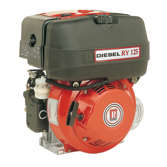
Summary of Contents for Ruggerini RY125 Series
- Page 1 WORK SHOP MANUAL RY 125 series engines, p.no. 1-5302-633 RY125 Edition COMPILER TECO/ATI REG. CODE MODEL N° DATE OF ISSUE DATE ENDORSED REVISION 1-5302-633 51074 02-04 29.02.2004...
-
Page 2: General Service Notes
FOREWORD We have done all in our power to give up to date and accurate technical information in this manual. Ruggerini engines are, however, constantly developing thus the data in this publication may be liable to modification without prior notice. -
Page 3: Warranty Certificate
Within the above stated periods Lombardini Srl directly or through the Ruggerini Motori authorized network will repair and/or replace free of charge any own part or component that, upon examination by Ruggerini Motori Service Dept. or by an authorized Ruggerini Motori agent, is found to be defective in conformity, workmanship or materials. -
Page 4: Table Of Contents
INDEX This manual contains pertinent information regarding the repair of RUGGERINI air-cooled, indirect injection Diesel engines type RY125: updated February 29, 2004. TROUBLE SHOOTING __________________________________________________________ Page SAFETY AND WARNING DECALS - SAFETY INSTRUCTIONS ____________________________ " MODEL NUMBER AND IDENTIFICATION _____________________________________________ "... - Page 5 INDEX INJECTION EQUIPMENT ________________________________________________________ Page Checking the injection pump ............................26 Demounting and remounting ............................28 Fuel circuit ..................................25 Injection pump ................................25 Injection pump assembly ............................... 26 Injection pump calibration .............................. 26 Injector ..................................... 27 Injector inspection and calibration ..........................27 Leak test ..................................
- Page 6 INDEX ENGINE TESTING _____________________________________________________________ Page Braked engine test ................................39 Rpm regulation ................................39 STORAGE ___________________________________________________________________ Page Setting at work ................................. 40 Storage for up to 6 months ............................. 40 Storage periods of more than 6 months ........................40 QUICK REFERENCE CHARTS ____________________________________________________ Page Adjustments ..................................
-
Page 7: Trouble Shooting
TROUBLE SHOOTING POSSIBLE CAUSES AND TROUBLE SHOOTING The following table contains the possible causes of some failures which may occur during operation. Always perform these simple checks before removing or replacing any part. TROUBLE POSSIBLE CAUSE Clogged pipes Clogged fuel filter Air inside fuel circuit Clogged tank breather hole Faulty fuel pump... -
Page 8: Safety And Warning Decals - Safety Instructions
SAFETY INSTRUCTIONS • Ruggerini Engines are built to supply their performances in a safe and long-lasting way. To obtain these results, it is essential for users to comply with the servicing instructions given in the relative manual along with the safety recommendations listed below. - Page 9 • Only check belt tension when the engine is off. • Only use the eyebolts installed by Ruggerini to move the engine. These lifting points are not suitable for the entire machine; in this case, the eyebolts installed by the manufacturer should be used.
-
Page 10: Model Number And Identification
MODEL NUMBER AND IDENTIFICATION MODEL NUMBER ENGINE IDENTIFICATION Model Engine Serial Number Approval code Customer's code R.P.M. setting R.P.M. Displacement (cc) COMPILER TECO/ATI REG. CODE MODEL N° DATE OF ISSUE DATE ENDORSED REVISION 1-5302-633 51074 02-04 29.02.2004... -
Page 11: Technical Data
TECHNICAL DATA CHARACTERISTICS ENGINE TYPE RY125 Number of cylinders Bore Stroke Swept volume cm³ Compression ratio 19:1 N 80/1269/CEE-ISO 1585 9 (12.24) Power kW (HP) NB ISO 3046 - 1 IFN 8.4 (11.42) NA ISO 3046 - 1 ICXN 7.6 (10.34) Crankshaft PTO ratio 3600 Camshaft PTO ratio... -
Page 12: Vcharacteristics
Max. power tolerance is 5%. Power decreases by approximately 1% every 100 m di altitude and by 2% every 5°C above 25°C. Note: Consult RUGGERINI for power, torque curves and specific consumptions at rates differing from those given above. COMPILER TECO/ATI REG. -
Page 13: Overall Dimensions
OVERALL DIMENSIONS PRESA DI FORZA STANDARD CON SENSO DI ROTAZIONE PRESA DI FORZA SU ALBERO A CAMME OPZIONALE CON SENSO SINISTRO DI ROTAZIONE DESTRO STANDARD P.T.O. WITH ANTICLOCKWISE DIRECTION OF OPTIONAL P.T.O. ON CAMSHAFT WITH CLOCKWISE DIRECTION OF ROTATION ROTATION Note: Dimensions in mm COMPILER TECO/ATI REG. -
Page 14: Special Tools
SPECIAL TOOLS TOOL CODE DESCRIPTION 00365R0020 Flywheel puller 00365R0900 Tool to mount and demount main bearings 00366R0220 Plug to mount and demount main bearings 00366R0230 Sleeve to insert main bearings 00365R0770 Piston mounting tool 00365R0100 Crankshaft gear puller 00366R0210 Punch to insert By-pass valve 00365R0430 Injector test bench 00366R0240... -
Page 15: Maintenance - Recommended Oil Type - Refilling
MAINTENANCE - RECOMMENDED OIL TYPE - REFILLING VIII Failure to carry out the operations described in the table may lead to technical damage to the machine and/or system MANUTENANCE INTERVAL (HOURS) OPERATION 2500 5000 • SUMP OIL LEVEL CHECK • OIL BATH AIR CLEANER CLEANING •... -
Page 16: Viii Maintenance - Recommended Oil Type - Refilling
VIII MAINTENANCE - RECOMMENDED OIL TYPE - REFILLING The engine could be damaged if allowed to operate with insufficient oil. It is also dangerous to add too much oil as its combustion could sharply increase the rotation speed. Use a suitable oil in order to protect the engine. The lubrication oil influences the performances and life of the engine in an incredible way. -
Page 17: Disassembly Of The Engine
DISASSEMBLY AND REASSEMBLY Besides disassembly and reassembly operations this chapter also includes checking and setting specifications, dimensions, repair and operating instructions. Always use original RUGGERINI spare parts for repair operations. Removing the injector Slacken off the fuel delivery pipe, remove the fixing bracket and take out the tube. -
Page 18: Demounting And Remounting The Main Bearings
DISASSEMBLY OF THE ENGINE Demounting the piston Take out the piston pin as shown in fig. 5. Warning: do not demount the head when hot or the retention surfaces could be damaged. Demounting and remounting the main bearings Use tool code 00365R0900 and plug code 00366R0220 (fig. 6) to Main bearing demount the main bearings from the engine casing and cover on the timing system side. -
Page 19: Head
CHECKS AND OVERHAUL Head Parts indicated in fig. 8. 1. Nut - 2.Nut with ball - 3. Rocker arm - 4. Cotters - 5. Rocker arm stud - 6. Upper cap - 7. Spring - 8. Air-relief valve - 9. Lower cap - 10. Valve guide - 11. -
Page 20: Xchecks And Overhaul
CHECKS AND OVERHAUL Grinding-in must always be carried out when new valves or housings are mounted. Valve housings oversized on the outside by 0.5 mm are available. Thoroughly wash the valve and housing with petroleum or gasoline to eliminate lapping paste residues or swarf. Proceed in the following way to make sure that the valve and seat are tight: 1. -
Page 21: Connecting Rod
CHECKS AND OVERHAUL Piston rings - Piston - Pin To gauge the wear on the piston rings, put them into the cylinder from the bottom side and measure the distance between the free ends (fig. 16), which must be: Fitting mm Max. -
Page 22: Crankshaft
CHECKS AND OVERHAUL The operation is carried out by applying a calibrated pressure to the convex side in the middle of the connecting rod stem set on surface plates (fig. 20). Crankshaft It is advisable to check the condition of the crankshaft whenever the engine is demounted and particularly when cylinders and pistons must be replaced following wear due to dust having been intaken. -
Page 23: Camshaft
CHECKS AND OVERHAUL Checking the oil pump Make sure that the oil pump cover is in a good condition. After demounting, examine the rotors and replace them if their lobes or centerings are damaged. To check the degree of pump wear, measure the dimensions of rotor A and rotor B (fig. -
Page 24: Fuel Pump (Optional)
CHECKS AND OVERHAUL Tapets and rocker arms Make sure that there is no wear, scoring or signs of seizure on the surfaces of the tappets (fig. 28). Replace the parts if necessary. Ø7,986 ÷ 7,995 Tapet and housing coupling play: Fitting mm Max. -
Page 25: Injection Equipment
INJECTION EQUIPMENT Fuel circuit Fuel supply is the gravitational type. An AC pump can be mounted on request. Air bleeding is automatic. Illustration in fig. 30: 1. Fuel tank - 2. Fuel pipe - 3. Fuel filter - 4. Injection pump - 5. Fuel return pipe - 6. -
Page 26: Checking The Injection Pump
INJECTION EQUIPMENT Checking the injection pump before demounting the injection pump, make sure that the plunger unit, enbloc pump casing and valve are pressure tight by proceeding in the following way: 1. Connect a pressure gauge with scale up to 600 Kg/cm² to the fuel delivery pipe (fig. -
Page 27: Injector
INJECTION EQUIPMENT 5. Insert the adjuster sleeve unit and plunger (L) into the pump casing (A), making sure that the helical profile is directed on a level with the return union with ball. 6. Fit in the adjuster block (M), matching the reference marks applied during the demounting phase. -
Page 28: Demounting And Remounting
INJECTION EQUIPMENT check the time it takes to drop. The pressure must drop to 150 to 100 Kg/cm² withinn 6 to 40 seconds. replace the nozzle if it drops in less than 6 seconds. if it takes longer than 40 seconds to drop, make sure that there are no carbon deposits in the nozzle and that the return holes are not clogged. -
Page 29: Electrical Equipment
ELECTRICAL EQUIPMENT Characteristics of the system Starter motor: lh rotation direction (pinion side), 12V voltage rating, power 1.1 kW. Internal alternator: 12V - 280W Voltage regulator: electronic, with controlled diodes and indicator connection for battery recharger Recommended battery: In standard start conditions: 12V - 50Ah/255 A DIN In heavy-duty start conditions: 12V - 60Ah/300 A DIN Optional accessories: control strip with remote control switch and OIL ALARM plant. -
Page 30: Checking The Alternator
ELECTRICAL EQUIPMENT Checking the alternator With the engine at a standstill, disconnect the alternator wires from the regulator and check: 1. using an ohmmeter, that the windings (fig. 45, null resistance) and the insulation between wires and ground (fig. 46, infinite resistance) are unbroken. -
Page 31: Engine Assembly
ENGINE ASSEMBLY XIII The instructions refer to engines updated at the time of publication. Check technical circulars modifications. Thoroughly clean the parts before remounting them. Lubricate the moving parts to prevent seizures when the engine is first started. Replace the seals whenever the parts are remounted. Use torque wrenches to tighten to the correct values. -
Page 32: Timing System Cover Pre-Assembly
ENGINE ASSEMBLY Timing system cover pre-assembly Prepare the cover of the timing system in the following way: 1. Mount the main bearing as indicated at page 18. 2. Fit in the pin and drive shaft bearing ring (fig 52). 3. Mount the oil pump rotors as described at page 23. Insert the plug and driving pin as shown in fig. -
Page 33: Connecting Rod - Drive Shaft Connection
ENGINE ASSEMBLY XIII Removal and assembly of the drive shaft gear The gear on the timing system side can only be replaced. To demount it, use puller code 00365R0100 (fig. 56) or a puller available on the market. To assemble, preheat the gear to a temperature of about 180 to 200 °C, fit it on the shaft, taking care to ensure that the chamfer points towards the internal part, and use the tang as a reference. -
Page 34: Camshaft
XIII ENGINE ASSEMBLY Camshaft Insert the tappets into their housings on the casing. Mount the camshaft, matching the reference marks on the gears (fig.60). Play adjustment Crankshaft float: Place a calibrated bar on the casing, on a level with the timing system cover retention surface and use a thickness gauge to check the distance between the gear and bar (fig. -
Page 35: Cover On Timing System Side
ENGINE ASSEMBLY XIII Counter-shaft float (optional): Place a calibrated bar on a level with the timing system cover retention surface and use a thickness gauge to check the distance between the stop surface and bar (fig. 64). The measured value must be between: 0,10 ÷... -
Page 36: Cylinder
XIII ENGINE ASSEMBLY Piston Mount the rings on the piston (fig. 68) in the following order: 1. chromium plated compression retention ring (stamped trademark pointing upwards) 2. tapering retention ring (stamped word TOP pointing upwards) 3. oil scraper ring (stamped trademark pointing upwards) Position the piston so that the central axis of the combustion chamber is aligned with the injector (fig. -
Page 37: Injection Lead
ENGINE ASSEMBLY XIII Insert the rocker arm casings, the partition (A, fig. 74), the head seal and the head. Tighten the head fixing nuts evenly and alternately (fig. 73) to the following value: 4 kgm (39,2 Nm) NOTE: To prevent oil leaks, apread sealant (Motorsil) on the threads of the stud bolts and washer bearing surfaces in the rocker arm chamber before tightening the nuts. -
Page 38: Injector And Injector Tube
XIII ENGINE ASSEMBLY Mounting the injection pump on the engine Lower the tappet in the innermost point of the engine by slightly turning the flywheel. Insert a seal of adequate thickness (see section "Injection lead" point 5, page 37). Turn the motor stop lever to the STOP position. Set the adjuster sleeve of the injection pump about one millimeter from the stop position on the adjuster block (fig. -
Page 39: Engine Testing
ENGINE TESTING Rpm regulation Fill the engine with oil and diesel fuel and allow it to warm up for 10 minutes. With the engine hot, adjust the idling rate (A, fig. 79) to 1,300 rpm and the peak no-load rate (B, fig. 79) to: - 3,150 rpm for engines set at 3,000 rpm on load - 3,750 rpm for engines set at 3,600 rpm on load Braked engine test... -
Page 40: Storage
STORAGE Storage Prepare engines as follows for storage over 30 days Temporary protection (1/6 months) • Let engine run at idling speed in no-load conditions for 15 minutes. • Fill crankcase with protection oil MIL-1-644-P9 and let engine run at 3/4 full speed for 5/10 minutes. •... -
Page 41: Quick Reference Charts
QUICK REFERENCE CHARTS Couplings Spiel (mm) Grezen (mm) Camshaft and plugs 0,032 ÷ 0,061 Compression ring opening 0,30 ÷ 0,50 Oil scraper ring opening 0,25 ÷ 0,50 Connecting rod and piston pin 0,023 ÷ 0,038 0,04 Injection pump tappets and housing 0,021 ÷... -
Page 42: Standard Screw Tightening Torques
QUICK REFERENCE CHARTS Tightening torques (Nm) Timing system cover 2,7 ÷ 2,8 26,5 ÷ 27,5 Injector ring nut 4,6 ÷ 5,6 45 ÷ 55 Injection tube unions 2 ÷ 2,5 19,6 ÷ 24,5 Injector bracket 0,8 ÷ 0,9 7,8 ÷ 8,8 Injection pump bracket 19,6 Head... -
Page 43: Service
SERVICE XVII SUGGESTIONS ON HOW TO TIME THE INJECTION PUMP WHEN THE LEAD PUNCH MARKS ON THE FLYWHEEL ARE DIFFICULT TO REACH. (Consult chapter "Injection lead" on page 37 for a description of the conventional adjustment) Proceed in the following way: 1. - Page 44 RUGGERINI MOTORI Via Cav. del Lavoro A. Lombardini, 2 42100 REGGIO EMILIA - Italia - ITALY Tel. (+39) 0522 3891 - Fax (+39) 0522 389433/465 http://www.ruggerini.it è un marchio della La Lombardini si riserva il diritto di modificare in qualunque momento i dati contenuti in questa pubblicazione.
Need help?
Do you have a question about the RY125 Series and is the answer not in the manual?
Questions and answers