
Related Manuals for TSI Instruments SUREFLOW 8682

Summary of Contents for TSI Instruments SUREFLOW 8682
- Page 1 ENERGY AND COMFORT Critical Environments Monitors/Controllers Models 8682 8682-BAC ™ Adaptive Offset Controller Operation and Service Manual P/N 1980483, Revision D January 2008...
- Page 3 Models 8682 8682-BAC ™ Adaptive Offset Controller Operation and Service Manual P/N 1980483, Revision D January 2008 U.S. AND CANADA OTHER COUNTRIES Sales & Customer Service: Sales & Customer Service: (800) 874-2811/(651) 490-2811 (001 651) 490-2811 Fax: Fax: (651) 490-3824 (001 651) 490-3824 SHIP/MAIL TO: E-MAIL...
- Page 4 Copyright ©- TSI Incorporated / Revision D / 2008 / All rights reserved. Part number 1980483 LIMITATION OF WARRANTY AND LIABILITY Seller warrants the goods sold hereunder, under normal use and service as described in the operator's manual, shall be free from defects in workmanship and material for twenty-four (24) months, or the length of time specified in the operator's manual, from the date of shipment to the customer.
-
Page 5: Table Of Contents
CONTENTS HOW TO USE THIS MANUAL ..................IV PART ONE.......................... 1 User Basics ....................1 The Instrument..................1 Operator Panel..................3 Alarms ....................... 5 Before Calling TSI..................6 PART TWO ......................... 7 Technical Section..................7 Software Programming ................7 Menu and Menu Items ................11 Setup / Checkout .................. -
Page 6: How To Use This Manual
How to Use This Manual The S ™ Operation and Service Manual is divided into two parts. Part One describes how the S unit functions and how to interface with the device. This section should be read by users, facilities staff, and anyone who requires a basic understanding of how the controller operates. -
Page 7: Part One
PART ONE User Basics Part One provides a brief but thorough overview of the S ™ product by maximizing information with minimal reading. These few pages explain the purpose (The Instrument), and the operation (Useful User Information, Digital Interface Module, Alarms) of the unit. Technical product information is available in Part Two of the manual. - Page 8 The S device informs the laboratory users when the laboratory is under proper pressure, and provides alarms when the room pressure is inadequate. If the room pressure is in the safe range, a green light is on. If the pressure is inadequate, a red alarm light and audible alarm turn on. The S controller consists of three pieces: pressure sensor, Digital Interface Module (DIM), and Adaptive Offset Controller (AOC).
-
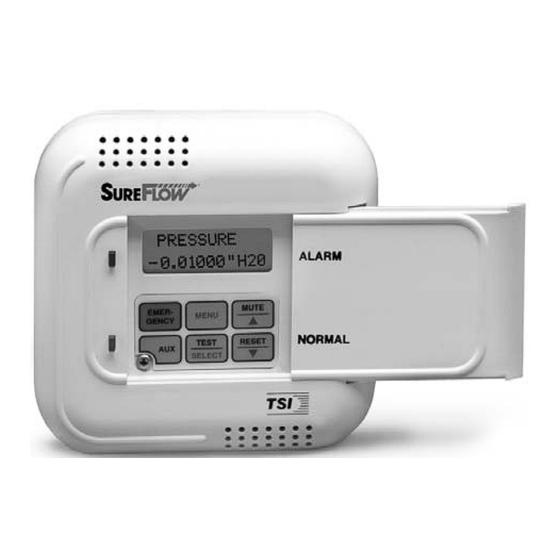
Page 9: Operator Panel
Operator Panel The DIM in Figure 3 shows the location of the digital display, keypad and lights. An explanation of the operator panel follows the figure. Figure 3: S Operator Panel–Open Green / Red Light The green light is on when all the conditions for proper room pressure are adequate. This light indicates the laboratory is operating safely. - Page 10 User Keys - Gray with Black Letters The four keys with black letters provide you information without changing the operation or the function of the unit. TEST Key The TEST key initiates an instrument self-test. Pressing the TEST key activates a scrolling sequence on the display that shows the product model number, software version, and all set point and alarm values.
-
Page 11: Alarms
Emergency Key - Red with Black Letters EMERGENCY Key The red EMERGENCY key puts the controller into emergency mode. If the room is under negative room pressure control, the emergency mode will maximize the negative pressure. Conversely, if the room is under positive room pressure control, the emergency mode will maximize the positive pressure. -
Page 12: Before Calling Tsi
Before Calling TSI This manual should answer most questions and resolve most problems you may encounter. If you need assistance or further explanation, contact your local TSI representative or TSI. TSI is committed to providing high quality products backed by outstanding service. Please have the following information available prior to contacting your authorized TSI Manufacturer's Representative or TSI: •... -
Page 13: Part Two
PART TWO Technical Section The AOC is ready to use after being properly installed. The pressure sensor is factory calibrated prior to shipping and should not need adjustment. The flow stations must be calibrated prior to using them. The Digital Interface Module (DIM) is programmed with a default configuration that can be easily modified to fit your application. - Page 14 Figure 4: Programming Keys MENU Key The MENU key has three functions. The MENU key is used to gain access to the menus when the unit is in the normal operating mode. Pressing the key once will exit the normal operating mode and enter the programming mode.
- Page 15 Keystroke Procedure The keystroke operation is consistent for all menus. The sequence of keystrokes is the same regardless of the menu item being changed. Press the MENU key to access the main menu. Use the keys to scroll through the menu choices. The blinking cursor needs to be on the first letter of the menu you want to access.
- Page 16 Press the key once. HIGH ALARM will be shown on display. Menu selected ALARM Item name HIGH ALARM Press the SELECT key to access the high alarm set point. The item name (HIGH ALARM) will now be displayed on line 1 and the item's current value will be displayed on line 2.
-
Page 17: Menu And Menu Items
Menu and Menu Items The S controller is a very versatile device which can be configured to meet your specific application. This section describes all of the menu items available to program and change. Changing any item is accomplished by using the keypad, or if communications are installed, through the RS-485 Communications port. - Page 18 INPUT CHECK INTERFACE SUPPLY FLOW EXHAUST FLOW SUP 1 NET PROTOCOL* SP1 DCT AREA EX1 DCT AREA SUP 2 NET ADDRESS* SP2 DCT AREA EX2 DCT AREA SUP 3 LON* SP3 DCT AREA EX1 FLO ZERO SUP 4 MAC ADDRESS* SP4 DCT AREA EX2 FLO ZERO EXH 1...
- Page 19 SET POINTS MENU SOFTWARE DEFAULT MENU ITEM NAME ITEM DESCRIPTION ITEM RANGE VALUE PRESSURE SET SET POINT The SET POINT item sets the pressure control set point. The O or 0 to -0.19000 in. H -0.00100” H POINT controller will maintain this set point, negative or 0 to +0.19000 H positive, under normal operating conditions.
- Page 20 SET POINTS MENU (continued) SOFTWARE DEFAULT MENU ITEM NAME ITEM DESCRIPTION ITEM RANGE VALUE COOLING The COOLING FLOW item sets the space cooling supply SPACE COOLING 0-30,000 CFM SUPPLY FLOW FLOW airflow set point (CFM). This item defines a supply air flow (0-14,100 l/s) SET POINT intended to meet the space’s cooling requirements by allowing...
- Page 21 SET POINTS MENU (continued) SOFTWARE DEFAULT MENU ITEM NAME ITEM DESCRIPTION ITEM RANGE VALUE UNOCCUPY The UNOCCUPY SET item sets a minimum supply flow set UNOCCUPIED 0-30,000 CFM SUPPLY FLOW point when the laboratory is unoccupied (requires fewer air (0-14,100 l/s) MINIMUM changes per hour).
- Page 22 SET POINTS MENU (continued) SOFTWARE DEFAULT MENU ITEM NAME ITEM DESCRIPTION ITEM RANGE VALUE MIN EXH The MIN EXH SET item sets the minimum general exhaust air MINIMUM 0-30,000 CFM EXHAUST FLOW flow out of the laboratory. The controller will not allow the (0-14,100 l/s) SET POINT general exhaust air damper to close further than the MIN EXH...
-
Page 23: Alarm Menu
SET POINTS MENU (continued) SOFTWARE DEFAULT MENU ITEM NAME ITEM DESCRIPTION ITEM RANGE VALUE END OF The END OF MENU item informs you that the end of a menu MENU has been reached. You can either scroll back up the menu to make changes, or press the SELECT or MENU key to exit out of the menu. - Page 24 ALARM MENU (continued) SOFTWARE DEFAULT MENU ITEM NAME ITEM DESCRIPTION ITEM RANGE VALUE MINIMUM MIN SUP The MIN SUP ALM item sets the supply flow alarm set point. A 0-29,950 CFM SUPPLY FLOW minimum flow alarm is defined as when the supply duct flow is (0-14,125 l/s) ALARM less than the MIN SUP ALM set point.
- Page 25 ALARM MENU (continued) SOFTWARE DEFAULT MENU ITEM NAME ITEM DESCRIPTION ITEM RANGE VALUE AUDIBLE AUDIBLE The AUDIBLE ALM item selects whether the audible alarm is ON or OFF ALARM turned ON or OFF. Selecting ON requires the staff to press the MUTE key to silence the audible alarm.
- Page 26 ALARM CONSTRAINTS There are a number of constraints built into the software that prevent users from programming conflicting alarm information. These are as follows: 1. The AOC does not allow the pressure alarms to be programmed within 20 ft/min (0.00028 in. H O at 0.001 in.
- Page 27 CONFIGURE MENU SOFTWARE DEFAULT MENU ITEM NAME ITEM DESCRIPTION ITEM RANGE VALUE DISPLAY UNITS UNITS The UNITS item selects the unit of measure that the DIM FT/MIN, m/s, in. H "H displays all values (except calibration span). These units display for all menu items set points, alarms, flows, etc.
- Page 28 CALIBRATION MENU SOFTWARE DEFAULT MENU ITEM NAME ITEM DESCRIPTION ITEM RANGE VALUE SENSOR SPAN SENSOR The SENSOR SPAN item is used to match or calibrate the TSI NONE SPAN pressure sensor (velocity sensors) to the average room pressure velocity as measured by a portable air velocity meter. Unit is factory calibrated.
- Page 29 CONTROL MENU SOFTWARE DEFAULT MENU ITEM NAME ITEM DESCRIPTION ITEM RANGE VALUE SPEED SPEED The SPEED item is used to select the control output speed 1 to 10 bars 5 bars (supply and general exhaust). When this item is selected, a bar graph is shown on the display.
- Page 30 CONTROL MENU (continued) SOFTWARE DEFAULT MENU ITEM NAME ITEM DESCRIPTION ITEM RANGE VALUE CONTROL The CONTROL SIG item switches both the supply and exhaust CONTROL SIGNAL 4–20 mA or 0–10 VDC 0-10 VDC control outputs from 0–10 VDC to 4–20 mA. TSI actuators require a 0-10 VDC control signal.
- Page 31 CONTROL MENU (continued) SOFTWARE DEFAULT MENU ITEM NAME ITEM DESCRIPTION ITEM RANGE VALUE Kc VALUE Kc VALUE WARNING: The Kc VALUE and Ti VALUE allow you to Kc = 0–1000 Kc = 80 Ti VALUE Ti VALUE manually change the primary PID control loop Ti = 0-1000 Ti = 200 variables.
- Page 32 CONTROL MENU (continued) SOFTWARE DEFAULT MENU ITEM NAME ITEM DESCRIPTION ITEM RANGE VALUE Kc OFFSET Kc OFFSET WARNING: The Kc OFFSET sets the pressure control PID Kc = 0–1000 Kc = 200 variable. DO NOT CHANGE THIS VALUE UNLESS YOU HAVE A THOROUGH The range of values is very large.
- Page 33 CONTROL MENU (continued) SOFTWARE DEFAULT MENU ITEM NAME ITEM DESCRIPTION ITEM RANGE VALUE TEMP DB The TEMP DB item determines the controller’s temperature TEMPERATURE ±0.0°F to ±1.0°F ±0.3°F SENSITIVITY control deadband, which is defined as the temperature range above and below the temperature set point (TEMP SETP), where the controller will not take corrective action.
- Page 34 CONTROL MENU (continued) SOFTWARE DEFAULT MENU ITEM NAME ITEM DESCRIPTION ITEM RANGE VALUE TEMPERATURE TEMP TR The TEMP TR item determines the controller’s temperature 2.0°F to 20.0°F 6.0°F THROTTLING control throttling range, which is defined as the temperature RANGE range for the controller to fully open and fully close the reheat valve.
- Page 35 CONTROL MENU (continued) SOFTWARE DEFAULT MENU ITEM NAME ITEM DESCRIPTION ITEM RANGE VALUE TEMPERATURE TEMP TI WARNING: The TEMP TI item provides you with the ability 0 to 10,000 seconds 2400 seconds INTEGRAL TIME to manually change the temperature control loop algorithm.
- Page 36 SYSTEM FLOW MENU SOFTWARE DEFAULT MENU ITEM NAME ITEM DESCRIPTION ITEM RANGE VALUE TOTAL SUPPLY TOT SUP The TOT SUP FLOW menu item displays the current total NONE AIR FLOW FLOW measured supply flow into the laboratory. This item calculates NONE: Read only total supply by summing SP1 FLOW IN though SP4 FLOW value...
- Page 37 SYSTEM FLOW MENU (continued) SOFTWARE DEFAULT MENU ITEM NAME ITEM DESCRIPTION ITEM RANGE VALUE EXH SET The EXH SET POINT menu item displays the general exhaust GENERAL NONE EXHAUST FLOW POINT flow set point, which is calculated by the AOC control NONE: Read only SET POINT algorithm.
- Page 38 FLOW CHECK MENU SOFTWARE DEFAULT MENU ITEM NAME ITEM DESCRIPTION ITEM RANGE VALUE INDIVIDUAL SP1 FLOW The SP# FLOW IN menu item displays the current supply air NONE SUPPLY AIR FLOW flow. This item is a diagnostics tool used to compare the supply NONE: Read only SP2 FLOW flow to a traverse of the duct work.
-
Page 39: Flow In
FLOW CHECK MENU (continued) SOFTWARE DEFAULT MENU ITEM NAME ITEM DESCRIPTION ITEM RANGE VALUE INDIVIDUAL HD1 FLOW The HD# FLOW IN menu item displays the current exhaust NONE FUME HOOD flow from a fume hood. This item is a diagnostics tool to NONE: Read only through FLOW IN... -
Page 40: Outputs
DIAGNOSTICS MENU SOFTWARE MENU ITEM NAME ITEM DESCRIPTION SUPPLY AIR CONTROL The CONTROL SUP item manually changes the control output signal to the supply air actuator/damper (or motor CONTROL speed drive). When this item is entered, a value between 0% OPEN and 100% OPEN will be shown on the display OUTPUT indicating the control output value. - Page 41 DIAGNOSTICS MENU (continued) SOFTWARE MENU ITEM NAME ITEM DESCRIPTION SENSOR The SENSOR STAT item verifies that the RS-485 communications between the pressure sensor and DIM is SENSOR COMMUNICATION STAT working correctly. Pressure sensor error messages do not display on DIM except when SENSOR STAT item is selected.
- Page 42 DIAGNOSTICS MENU (continued) SOFTWARE MENU ITEM NAME ITEM DESCRIPTION REMOTE The REMOTE SWT item reads the input of the REMOTE SWT contact pins 3 and 4. When this item is entered, REM SET POINT INPUT the display will indicate either open or closed. If the display indicates open, the AOC uses the SET POINT pressure set point.
- Page 43 DIAGNOSTICS MENU (continued) SOFTWARE MENU ITEM NAME ITEM DESCRIPTION EXHAUST The EXHAUST AOUT item is used to verify the analog outputs are working. When this item is entered, the EXHAUST ANALOG OUTPUT AOUT number shown on the display indicates the last analog output value. The value displayed ranges from 0 to 255. The value 255 corresponds to 0 volts (4 mA) output and 0 corresponds to 10 volts (20 mA) output.
- Page 44 INPUT CHECK MENU SOFTWARE DEFAULT MENU ITEM NAME ITEM DESCRIPTION ITEM RANGE VALUE INDIVIDUAL SUP 1 When one of these items is entered, a voltage, representing the NONE SUPPLY FLOW through corresponding flow input, will be displayed. If the voltage NONE: Read only SIGNAL CHECK displayed is negative, double check the polarity of the flow...
- Page 45 INTERFACE MENU SOFTWARE DEFAULT MENU ITEM NAME ITEM DESCRIPTION ITEM RANGE VALUE NETWORK The NET PROTOCOL item selects the communications MODBUS, N2, MODBUS PROTOCOL** PROTOCOL protocol used to interface with the building management system. If LONWORK’s interface is being used, this menu item is deleted;...
-
Page 46: Analog Outputs
INTERFACE MENU (continued) SOFTWARE DEFAULT MENU ITEM NAME ITEM DESCRIPTION ITEM RANGE VALUE MAC ADDRESS** The MAC ADDRESS assigns the device an address on the 1-127 ADDRESS MS/TP BACnet network. This address must be unique for each device on the BACnet network. ANALOG OUTPUT The OUTPUT RANGE item selects the resolution range of the... - Page 47 INTERFACE MENU (continued) SOFTWARE DEFAULT MENU ITEM NAME ITEM DESCRIPTION ITEM RANGE VALUE CONFIGURE MAX FLOW The MAX FLOW OUT item scales the flow analog outputs, 1,000, 5,000, 10,000, 10,000 MAXIMUM FLOW pins 50, 51, 52, 53. The value selected equates to 10 volts or 20 20,000, 30,000 CFM OUTPUT mA.
- Page 48 SUPPLY FLOW MENU SOFTWARE DEFAULT MENU ITEM NAME ITEM DESCRIPTION ITEM RANGE VALUE SUPPLY AIR DUCT SP1 DCT The SP# DCT AREA item inputs the supply air exhaust duct 0–10 square feet AREA SIZES size. The duct size is needed to compute the supply air flow (0–0.9500 square into the laboratory.
- Page 49 SUPPLY FLOW MENU (continued) SOFTWARE DEFAULT MENU ITEM NAME ITEM DESCRIPTION ITEM RANGE VALUE MAXIMUM FLOW The TOP VELOCITY item is used to input the maximum 0–5,000 FT/MIN VELOCITY velocity of a linear flow station output. A TOP VELOCITY STATION (0–25.4 m/s) VELOCITY must be input for the linear flow station to operate.
- Page 50 SUPPLY FLOW MENU (continued) SOFTWARE DEFAULT MENU ITEM NAME ITEM DESCRIPTION ITEM RANGE VALUE RESET RESET CAL The RESET CAL menu item restores the default calibration CALIBRATION for the 4 supply flows. When this menu item is entered, the 8682 will prompt the user to verify that they want to do this by indicating NO.
- Page 51 EXHAUST FLOW MENU SOFTWARE DEFAULT MENU ITEM NAME ITEM DESCRIPTION ITEM RANGE VALUE GENERAL EX1 DCT The EX# DCT AREA item inputs the general exhaust duct 0–10 square feet AREA EXHAUST DUCT size. The duct size is needed to compute the total general (0–0.9500 square SIZES exhaust flow out of the laboratory.
- Page 52 EXHAUST FLOW MENU (continued) SOFTWARE DEFAULT MENU ITEM NAME ITEM DESCRIPTION ITEM RANGE VALUE MAXIMUM FLOW The TOP VELOCITY item is used to input the maximum 0–5,000 FT/MIN VELOCITY velocity of a linear flow station output. A TOP VELOCITY STATION (0–25.4 m/s) VELOCITY must be input for the linear flow station to operate.
- Page 53 EXHAUST FLOW MENU (continued) SOFTWARE DEFAULT MENU ITEM NAME ITEM DESCRIPTION ITEM RANGE VALUE RESET RESET CAL The RESET CAL menu item restores the default calibration for CALIBRATION the 2 exhaust flows. When this menu item is entered, the 8682 will prompt the user to verify that they want to do this by indicating NO.
- Page 54 HOOD FLOW MENU SOFTWARE DEFAULT MENU ITEM NAME ITEM DESCRIPTION ITEM RANGE VALUE FUME HOOD HD1 DCT The HD# DCT AREA item inputs the fume hood exhaust 0–10 square feet EXHAUST DUCT AREA duct size. The duct size is needed to compute the flow out of (0–0.9500 square meters) SIZE the fume hood.
- Page 55 HOOD FLOW MENU (continued) SOFTWARE DEFAULT MENU ITEM NAME ITEM DESCRIPTION ITEM RANGE VALUE The TOP VELOCITY item is used to input the maximum MAXIMUM FLOW 0–5,000 FT/MIN STATION VELOCITY velocity of a linear flow station output. A TOP VELOCITY (0–25.4 m/s) VELOCITY must be input for the linear flow station to operate.
- Page 56 HOOD CAL MENU SOFTWARE DEFAULT MENU ITEM NAME ITEM DESCRIPTION ITEM RANGE VALUE HOOD # LOW HD1 LOW The HD# LOW CAL menu items display the currently CALIBRATION measured fume hood flow rate and the calibrated value for POINTS that fume hood flow. The calibrated hood flow can be through adjusted using the keys to make it match a reference...
-
Page 57: Setup / Checkout
Setup / Checkout The AOC is easy to program and setup. This section covers the theory of operation, required software programming, a programming example, and how to verify (checkout) that the components are functioning correctly. The AOC uses a unique control sequence that combines flow and pressure differential measurements to maintain air balance and laboratory pressure, while interfacing with a temperature sensor to maintain laboratory temperature. - Page 58 Temperature control The Model 8682 receives a temperature input from a temperature sensor (1000 Ω Platinum RTD). The Model 8682 controller maintains temperature control by: (1) Controlling supply and general exhaust for ventilation and cooling (2) Controlling the reheat coil for heating The Model 8682 has three supply flow minimum set points.
- Page 59 In summary, understanding the AOC control algorithm is the key to getting the system functioning correctly. The AOC control algorithm functions as follows: GENERAL FUME HOOD SUPPLY AIR EXHAUST + EXHAUST - OFFSET Supply air is at General exhaust is Independent control loop Programmed by minimum position;...
- Page 60 Programming Example The laboratory shown is Figure 7 is being initially setup. The required HVAC information is below the figure. Figure 7: Laboratory Setup Example Laboratory design: Laboratory size = 18’ x 30’ x 10’ (5,400 ft 5 foot fume hood (4) = 250 CFM min* 1,000 CFM max* Flow offset = 300–1000 CFM*...
- Page 61 Temperature Control System: Temperature Sensor (1000 Ω Platinum RTD) mounted in the laboratory. Reheat coil mounted in supply air duct(s). Fume Hood Control System: Independent S VAV Face Velocity Control system. Based on the preceding information, and knowing duct sizes, the following required menu items can be programmed: MENU ITEM ITEM VALUE...
- Page 62 However, the Digital Interface Module indicates the laboratory is now –0.0002 in. H O (not negative enough). The AOC algorithm slowly changes the offset until pressure control is maintained. In this case the offset changes to 400 CFM, which decreases the supply volume by 100 CFM.
- Page 63 NOTE: These checks require power to the AOC and all components. CHECK - DIM Press TEST key to verify Digital Interface Module (DIM) electronics are functioning correctly. At the end of the self test, the display will show SELF TEST - PASSED if DIM electronics are good.
-
Page 64: Calibration
CHECK - Sensor input Enter SENSOR INPUT menu item in diagnostics menu. A voltage between 0 and 10 volts DC will be displayed. It is not important what the exact voltage is to pass this test. Tape over the pressure sensor (slide pressure sensor door open) and voltage should read approximately 5 volts (zero pressure). - Page 65 Calibrating Pressure Sensor Enter calibration menu (see Software Programming if not familiar with keystroke procedure). Access code is turned on so enter access code. All menu items described below are found in CALIBRATION menu. Elevation The ELEVATION item eliminates pressure sensor error due to elevation of building. (See ELEVATION item in Menu and Menu items section for further information).
- Page 66 Flow Station Pressure Transducer Zero NOTE: Not required for linear flow stations with 0-10 VDC output. Pressure based flow station Disconnect tubing between pressure transducer and flow station. Enter menu that corresponds to flow station: Supply Flow, Exhaust Flow, or Hood Flow. Select SP# FLO ZERO to take a supply flow station zero.
- Page 67 Select SP HIGH SETP to enter a supply flow low calibration set point. Select EX HIGH SETP to enter a general exhaust flow low calibration set point. The DIM will display a value between 0% OPEN and 100% OPEN. Press the keys to adjust the value displayed (and the damper position).
-
Page 68: Maintenance And Repair Parts
NOTE: Insert number of flow calibration you are performing. A low flow calibration must be performed before its associated high flow calibration is performed. For example, in a laboratory that has two separate supply flows, SP1 LOW CAL must be completed before SP1 HIGH CAL. SP2 LOW CAL must be completed before SP2 HIGH CAL. -
Page 69: Lon
Use extreme care when cleaning the velocity sensors. The ceramic sensor may break if excessive pressure is applied, if sensor is scraped to remove contaminants, or if the cleaning apparatus abruptly impacts the sensor. WARNING: If you are using a liquid to clean the sensor, turn off power to the Model 8682. -
Page 70: Troubleshooting Section
Troubleshooting Section The S Room Pressure Controller is designed to be trouble free. However, installation problems or interaction with other HVAC components may cause system problems. The system is easy to troubleshoot if an organized approach to evaluate the system is taken. - Page 71 TEST - DIM Press TEST key to verify Digital Interface Module (DIM) electronics are functioning correctly. At the end of the self test, the display will show SELF TEST - PASSED if all DIM electronics are good. If unit displays DATA ERROR at the end of the test, the electronics may be corrupted.
- Page 72 over the pressure sensor (slide pressure sensor door open) and voltage should read approximately 5 volts (zero pressure). Remove tape and blow on sensor. Displayed value should change. If voltage changes, the unit passes. If voltage doesn’t change, proceed to TEST - Sensor status.
- Page 73 Troubleshooting Chart Symptom Possible Cause Corrective Action Display is blank. Fuse is blown. Measure voltage at pins 33 and 34 on AOC. The voltage should nominally be 24–30 VAC. If correct voltage is measured, internal DIM fuse is probably blown. Unplug 14-pin connector from DIM for 2 minutes.
- Page 74 Symptom Possible Cause Corrective Action Control system is No control output Go into DIAGNOSTICS menu, CONTROL SUP or CONTROL not controlling. signal. EXH item. A number between 0% OPEN and 100% OPEN will be (continued) displayed. Pressing the key increases the number. Pressing the key decreases the number.
- Page 75 Symptom Possible Cause Corrective Action Control system is Damper is full open Actuator jumper is missing or loose. Verify jumper is installed not controlling or full closed, won’t correctly. (continued) move. Control wires are loose. Check wires and verify control output is working (see no control output signal).
- Page 76 Symptom Possible Cause Corrective Action DIM always Incorrect pressure Pressure sensor must be set for 0-10 volt output, not 4–20 mA. Check displays 0.200 sensor output. pressure sensor DIP switch 3 and make sure it is OFF (see Figure 10). inches H DIM does not Network protocol is...
- Page 77 Symptom Possible Cause Corrective Action Go into CONTROL menu SPEED item, turn speed down until Displayed pressure Control system is wildly fluctuating. unstable. fluctuation is eliminated. If speed is too slow, review CONTROL menu items and adjust accordingly until performance is adequate. Exhaust system Turn DIM to emergency.
-
Page 79: Specifications
Appendix A Specifications Dim and AOC Module Display Range ................-0.20000 to +0.20000 inches H Accuracy ..............±10% of reading, ±0.00001 inches H Resolution ..............5% of reading Display Update............0.5 sec Inputs/Outputs See Wiring Information Appendix C for type. Switch in.............. - Page 80 Pressure Sensor Temperature Compensation Range ......55 to 95°F Power Dissipation ............0.16 watts at 0 inches H 0.20 watts at 0.00088 inches H Dimensions (DxH) ............5.58 in. × 3.34 in. × 1.94 in. Weight................. 0.2 lb. Damper/Actuator Types of Actuator............Electric Input Power ..............
-
Page 81: Network Communications
Appendix B Network Communications Network communications are available on the Model 8682. The Model 8682 can communicate with a building management system through Modbus, N2 or LonWorks protocols. The Model 8682-BAC can communicate with a building management system through BACnet MSTP protocol. Please refer to the appropriate section below for more detailed information. - Page 82 8682 Modbus Variable List Variable Integer DDC system Variable Name Address Input Provided to Master System receives Software Version Current Software Version 1.00 = 100 Controller Type Controller Model Number 8682 Emergency Mode Emergency Mode Control 0 Leave emergency mode 1 Enter emergency mode Control Mode Control mode of device.
- Page 83 Variable Integer DDC system Variable Name Address Input Provided to Master System receives Pressure Set point Pressure control set point Displayed in ft/min. Min Vent Set point Minimum flow set point for ventilation. Displayed in CFM. Cooling Flow Minimum flow set point for temperature Displayed in CFM.
- Page 84 QUERY RESPONSE Field Name (Hex) Field Name (Hex) Slave Address Slave Address Function Function Starting Address Hi Byte Count Starting Address Lo Data Hi No. Of Registers Hi Data Lo 8E (1000 CFM) No. Of Registers Lo Data Hi Error Check (CRC) Data Lo B0 (1200 CFM) Error Check (CRC)
-
Page 85: N2 Communications Description Of Variables
N2 Communications Description of Variables NPT - Network Point Type Variables are defined as analog inputs, binary inputs, and analog outputs. Analog inputs are current control parameters and items that the controller is measuring. Binary inputs represent controller states. Analog outputs are the programmable set points for the isolation room pressure controller and monitor. - Page 86 Supported Commands Command Response Request Device ID Returns 0x10 Synchronize Time Command Acknowledged. There Is No Internal Clock To Synchronize. Poll Without/With Ack Message Any Change Of Status Is Returned Read Analog Input Command Variable Value Read Binary Input Command Variable Value Read Analog Output Command Variable Value...
- Page 87 UNITS DESCRIPTION Min. Supply Flow Alarm 0=Normal 1=Low Flow Alarm Max. Exhaust Flow Alarm 0=Normal 1=High Flow Alarm Emergency Mode 0=Normal 1=Emergency Unoccupied Mode 0=Normal Mode 1=Unoccupied Mode Data Error 0=Normal 1=Data Error ft/min, m/s, in. Control Set point O, Pa ft/min, m/s, in.
-
Page 88: Lonworks Node Object
LonWorks Node Object Node Object Network variables nviRequest nvoStatus SNVT_obj_request SNVT_obj_status nviSetTime nvoAlarm SNVT_time_stamp SNVT_alarm nviMute nvoControlStatus SNVT_switch SNVT_char_ascii nvoStatusIndex SNVT_char_ascii Configuration properties nci 4 nciOutInht nci 165 nciDeviceIndex nci 166 nciFirmwareVer LON Works Room Controller Status Definitions nvoControlStatus nvoStatusIndex Description Description Standard... -
Page 89: Lonworks Object
LonWorks Object Adaptive Offset Controller Object nvoFlowOffset SNVT flow f nvoTotExhFlo SNVT flow nvoTotSupFlo SNVT flow nviSpaceTemp nvoSpaceTemp nv10 SNVT temp p SNVT temp p nviControlMode nvoRoomPress nv11 SNVT occupancy SNVT press f nvoTotGenExhFlo nviEmergMode nv12 SNVT flow SNVT hvac emerg nvoTotHoodExhFlo nviExhOverride nv13... -
Page 90: 8682 Bacnet Ms/Tp Protocol Implementation Conformance Statement
8682 BACnet MS/TP Protocol Implementation Conformance Statement Date: July 11, 2007 Vendor Name: TSI Inc. Product Name: S ™ Adaptive Offset Controller Product Model Number: 8682-BAC Applications Software Version: 1.0 Firmware Revision: 1.0 BACnet Protocol Revision: 2 Product Description: TSI S ™... - Page 91 Standard Object Types Supported: Dynamically Dynamically Optional Properties Writable Properties Createable Deletable Supported (Data Type) Analog Input Analog Value Present_Value (Real) Binary Input Active_Text, Inactive_Text Binary Value Active_Text, Present_Value Inactive_Text (Enumerated) Multi-state Input State_Text Multi-state Value State_Text Present_Value (Unsigned Int) Device Object Object Name (Char String)
-
Page 92: Model 8682-Bac Bacnet Ms/Tp Object Set
Model 8682-BAC BACnet MS/TP Object Set Device Object Type Instance *Units Description Analog Input ft/min, m/s, Room Pressure in. H O, Pa Analog Input cfm, l/s Total Supply Flow Analog Input Total General Exhaust cfm, l/s Flow Analog Input cfm, l/s Total Hood Flow Analog Input cfm, l/s... - Page 93 Device Object Type Instance *Units Description Analog Value cfm, l/s Min Supply Alarm 0 to 30,000 cfm Analog Value cfm, l/s Max Exhaust Alarm 0 to 30,000 cfm Analog Value °F, °C Temperature Set Point 50 to 85 °F Analog Value °F, °C Unocc Temp Set Point 50 to 85 °F...
-
Page 95: Wiring Information
Appendix C Wiring Information Back Panel Wiring Input / Output / PIN # Communication Description 1, 2 Input 24 VAC to power Digital Interface Module (DIM). NOTE: 24 VAC becomes polarized when connected to DIM. 3, 4 Output 24 VAC power for Pressure Sensor 5, 6 Input 0–10 VDC pressure sensor signal... - Page 96 Wiring Information (continued) Input / Output / PIN # Communication Description AOC (continued) 50, 51 Output 0–10 VDC, total supply flow - See menu item OUTPUT SIG 52, 53 Output 0–10 VDC, total exhaust flow - See menu item OUTPUT SIG 54, 55 Output Low supply flow alarm relay - N.O., closes in low flow condition.
- Page 97 WARNING: The wiring diagram shows polarity on many pairs of pins: ±, H / N, A / B. Damage to the DIM and AOC may occur if polarity is not observed. WARNING: Controller must be wired exactly as wire diagram shows. Making modifications to the wiring may severely damage the unit.
-
Page 99: Access Codes
Appendix D Access Codes There is one access code for all menus. If the access code is required to enter a menu, pressing the key sequence below will allow access to the menu. The access code must be entered within 40 seconds and each key must be pressed within 8 seconds. - Page 101 P/N 1980483 Rev. D Copyright © 2008 by TSI Incorporated Printed in U.S.A.
Need help?
Do you have a question about the SUREFLOW 8682 and is the answer not in the manual?
Questions and answers