Advertisement
NOTE:
Please read all instructions
carefully before using this
product
Table of Contents
Safety Notice
Hardware Identifier
Assembly Instruction
Parts List
Warranty
Ordering Parts
Model
MP-PWR10.0
Retain This
Manual for
Reference
04-08-05
OWNER'S
MANUAL
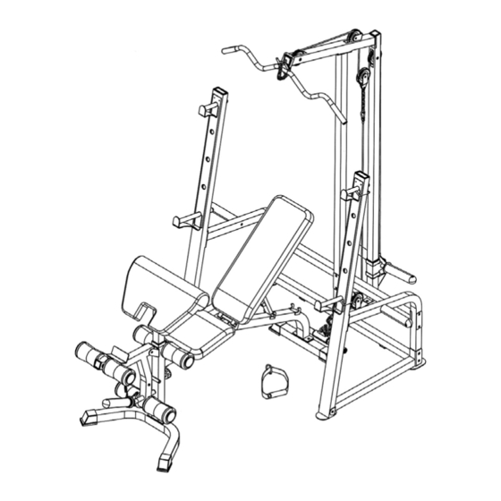
MARCY PLATINUM
MP-PWR 10.0
IMPEX FITNESS PRODUCTS
14777 DON JULIAN RD., CITY OF INDUSTRY, CA 91746
Tel: (800) 999-8899 Fax: (626) 961-9966
www.impex-fitness.com
info@impex-fitness.com
Advertisement

Summary of Contents for MPEX MARCY PLATINUM MP-PWR 10.0
- Page 1 NOTE: Please read all instructions carefully before using this product Table of Contents Safety Notice MARCY PLATINUM Hardware Identifier MP-PWR 10.0 Assembly Instruction Parts List Warranty Ordering Parts Model MP-PWR10.0 Retain This Manual for Reference 04-08-05 OWNER'S MANUAL IMPEX FITNESS PRODUCTS 14777 DON JULIAN RD., CITY OF INDUSTRY, CA 91746 Tel: (800) 999-8899 Fax: (626) 961-9966 www.impex-fitness.com...
-
Page 2: Table Of Contents
TABLE OF CONTENTS BEFORE YOU BEGIN..................1 IMPORTANT SAFETY NOTICES..............2 HARDWARE PACK………..…............... 3 ASSEMBLY INSTRUCTIONS................6 EXPLODED DIAGRAM.................………. 17 PARTS LIST………………………………………………………………………….. 19 WARRANTY....................… 20 ORDERING PARTS..................20 BEFORE YOU BEGIN Thank you for selecting the MARCY PLATINUM MP-PWR10.0 by IMPEX FITNESS PRODUCTS. -
Page 3: Important Safety Notice
IMPORTANT SAFETY NOTICE PRECAUTIONS This exercise machine is built for optimum safety. However, certain precautions apply whenever you operate a piece of exercise equipment. Be sure to read the entire manual before you assemble or operate your machine. In particular, note the following safety precautions: 1. - Page 5 HARDWARE PACK...
- Page 6 HARDWARE PACK...
-
Page 7: Assembly Instructions
ASSEMBLY INSTRUCTION Tools Required Assembling the Machine: Two Adjustable Wrenches and Allen Wrenches NOTE: It is strongly recommended this machine be assembled by two or more people to avoid possible injury. STEP 1 (See Diagram 1) A.) Attach the Main Frame (#27) to the Bench Front & Rear Stabilizers (#28 & 29). Secure each end with two M10 x ¾”... - Page 8 STEP 2 (See Diagram 2) A.) Attach the two side-holes on bottom of Backrest Supports (#30) to the pivot on the Main Frame (#27). Secure it with one M12 x 5 ¾” Allen Bolt (#75), two Ø 1” Washers (#68), and one M12 Aircraft Nut (#71).
- Page 9 STEP 3 (See Diagram 3) A.) Attach the Leg Developer (#33) to the open bracket on the Main Frame (#27). Secure it with one M10 x 3 1/8” Allen Bolt (#76), two Ø ¾” Washers (#69), and one M10 Aircraft Nut (#72).
- Page 10 STEP 4 (See Diagram 4) A.) Attach the Arm Curl Pad (#37) to the Arm Curl Stand (#32). Secure it with two M8 x ¾” Allen Bolts (#84) and two ∅ ¾” Washers (#70). Insert the Arm Curl Stand into the front opening on the Main Frame (#27) and secure it with a Lock Knob (#61) to hold it at the desired height.
- Page 11 STEP 5 (See Diagram 5) Note: Do not tighten the Nuts and Bolts until instructed to do so.
- Page 12 A.) Attach the top of Left Support (#2) to an Upright Beam (#1). Secure it with two M10 x 5/8” Allen Bolts (#82) and Ø ¾” Washers (#69). B.) Attach the Left Floor Stabilizer (#4) to the Upright Beam. Secure it with one M10 x 4” Carriage Bolt (#73), ∅...
- Page 13 STEP 6 (See Diagram 6) A.) Attach the Rear Vertical Frame (#9) onto the Rear Base (#8). Secure it with two M10 x 2 ½” Carriage Bolts (#74), Ø ¾” Washers (#69), and M10 Aircraft Nuts (#72). B.) Attach the Rear Base (#8) and Front Vertical Frame (#10) to the Rear Stabilizer (#7). Align the holes and secure them together with two M10 x 2 ½”...
- Page 14 CABLE LOOP DIAGRAM...
- Page 15 STEP 7 (See Diagram 7 & Cable Loop Diagram)
- Page 16 A.) Attach the 113 7/8” Upper Cable (#24) to the front opening on the Upper Frame (#11). Make sure the ball stopper of the Cable is underneath the Frame. B.) Attach a Pulley (#45) to the opening. Secure it with one M10 x 2 ½” Allen Bolt (#77), two 5/8” Pulley Bushings (#65), and one M10 Aircraft Nut (#72).
- Page 17 Frame (#10). Attach a Pulley (#45) to the opening and secure it with one M10 x 2 3/8” Allen Bolt (#78), two ½” Pulley Bushings (#66), and one M10 Aircraft Nut (#72). B.) Pull the Cable underneath the Pulley to the open bracket on the Rear Base (#8). Install a Pulley to the bracket with one M10 x 1 ¾”...
- Page 18 A.) Attach a Weight Post (#20) to the Right Support (#3). Secure it with a M10 x ¾” Allen Bolt (#81) and Ø ¾” Washer (#69). Slide an Olympic Sleeve (#44) onto the Post. Repeat the same procedure to install the other side. B.) Insert the Left &...
-
Page 20: Exploded Diagram
RACK EXPLODED DIAGRAM... -
Page 21: Parts List
PARTS LIST KEY NO. DESCRIPTION Q’ty Upright Beam 1 ¾” Square End Cap Left Support 2” Square End Cap Right Support Ø ½” Bushing Left Floor Stabilizer 1” Square End Cap Right Floor Stabilizer Ø 1” End Cap Cross Brace Foam Roll End Cap Rear Stabilizer 2”... -
Page 22: Limited Warranty
IMPEX INC. LIMITED WARRANTY IMPEX Inc. ("IMPEX") warrants this product to be free from defects in workmanship and material, under normal use and service conditions, for a period of two years on the Frame from the date of purchase. This warranty extends only to the original purchaser.
Need help?
Do you have a question about the MARCY PLATINUM MP-PWR 10.0 and is the answer not in the manual?
Questions and answers