
Summary of Contents for TrackSAT UltraTrack TS39
- Page 1 TrackSAT UltraTrack TS39 Installation and Operation User Manual Ku-BAND TVRO ANTENNA with Australian 10700 LNB Revision Ver. - 1.20...
- Page 2 This TrackSAT user manual has been developed as a guide to get the most delight and benefits from your Ku-band TVRO satellite antenna system. This operation manual includes information about TrackSAT UltraTrack TS-series equipment, installation, operating procedures, performance, and suggestions for its servicing and care.
-
Page 3: Table Of Contents
Contents page 1. Introduction …………………………………………………………………………………………………………………….…. 1 2. Installation .…………………………………………………………………………………………………………………….…... 2 2.1. Product Components ……………………………………………………………………………………………….…..2 2.1.1. Installation Kit List …………………………………………………………………………………………….………... 2 2.1.2. Required Tools ………………………………………………………………………………………………….………… 3 2.2. Safety Precautions ……………………………………………………………………………………………….………….. 3 2.3. Unpacking …………………………………………………………………………………………………………….………... 4 2.4. Selecting the Installation Site ………………………………………………………………………………….………... 4 2.4.1. - Page 4 3.3.5. Satellite Parameter Setting …………………………………………………………………………………….…… 20 3.3.6. Skew Angle Setting ……………………………………………………………………………………………….…... 21 3.3.6-a. Auto Mode …………………………………………………………………………………………………….…… 22 3.3.6-b. Manual Mode ……………………………………………………………………………………………….…….. 22 3.3.6-c. Trim ……………………………………………………………………………………………………………….…… 22 3.3.6-d. Reset …………………………………………………………………………………………………………….……. 23 3.3.6-e. Save …………………………………………………………………………………………………………….……... 23 3.3.6-f. Exit …………………………………………………………………………………………………………….……….. 23 3.3.7. Satellite Name Edit ……………………………………………………………………………………………….…… 23 3.3.8.
-
Page 5: Introduction
VAST set top boxes and also are compatible with Foxtel IQ boxes. The TS-series is a competitively priced antenna that is based on the same technology as the TrackSAT UltraTrack UT-series (TVRO), providing exceptional tracking ability, and is ideal for private and smaller vessels. -
Page 6: Installation
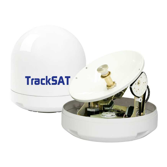
2. Installation 2.1 Product Components ① ADU (Above Deck Unit) the stabilized platform: contains the majority of hardware PCU (Pedestal Control Unit): controls electronics, movement system, and RF equipment RF Unit: receives optimum satellite signal from the Figure 1 - Radome satellite Radome: ultra-efficient plastic radome provides minimal loss and protect from... -
Page 7: Required Tools
2.1.2 Required Tools Figure 4 – Required Tools 2.2 Safety Precaution ADU module is sealed unit. This unit should be closed under any circumstances. The antenna radome assembly should be rigidly mounted on the boat. If necessary, reinforce the mounting area to assure that it does not flex due to the boat’s motion or vibration. -
Page 8: Unpacking
2.3. Unpacking ① Place the shipping box on a rigid, leveled surface. ② Inspect shipping box and note any damage. ③ Lift the unit out of the crate carefully ④ Move the antenna to its operating location (Using great care) ⑤... -
Page 9: Bdu (Below Deck Unit)
Figure 7 – Site Selection Example 2.4.2 BDU (Below deck Unit: ACU) The ACU (Antenna Controller Unit) will arrive with the TrackSAT control software pre-installed and will automatically run on the power up and also operation is largely automatic but it is desirable that it be monitored periodically. -
Page 10: Preparing The Mounting Surface
2.5.1 Preparing Mounting Surface ① Clean the surface where the antenna to be mounted ② Mark the 4 bolting holes position and center point for cables hole on the mounting surface. (see Figure – 9) ③ Make 4 bolt holes on the surface by using the power drill with 11mm drill bit. ④... -
Page 11: Adu Cable Connection
Figure 11 – Securing the Antenna Do not over-tighten. If the mounting bolt provided is too short, you will have to install mounting bolts of the appropriate length. If the bolt provided is too long, the excessive length should be cut off. 2.6 ADU Cable Connection Before starting the electric connection task, find the suitable location for laying the cables from BDU to ADU. -
Page 12: Acu Installation
④ use 11mm open-end wrench to connect the RF cables to the RF4/ACU cable ports on the bottom of the radome (see Figure – 12) ⑤ Inspect carefully all the cable connectors (F- type) are fully screwed in and all cabling from BDU is fully shielded and sealed. -
Page 13: Multi Ird Configuration
Connect the DC “power adapter cable” to the power connector from the power source 100 ① ~ 240 V AC. ② Connect the RF cable threaded from RF4 port on the ADU to the “Antenna port” on the ACU panel. ③... -
Page 14: Connecting The Ship Gyro
2.8 Connecting the Ship Gyro (optional) Your system is able to track the satellite without having ship gyro. Although your system can be operate without the ship gyro, user may directly connect vessel’s ship gyro to the antenna system when internal GPS is inoperative or to enhance the antenna’s searching capability that receiving vessel’s heading data will accelerate the searching speed by minimizing the searching range. -
Page 15: Operation
3. Operation To effectively control the UltraTrack TS-series antenna system, the user must understand and use functions in the ACU operation mode. 3.1 ACU Front Panel Layout Figure 18 – ACU Front Panel 3.1.1 ACU Main Display The KA-78 ACU shows essential data to allow the user determines the antenna system performance. -
Page 16: Led Indicator
3.1.2 LED Indicator ACU LED light indicator shows the status of an antenna tracking, GPS, and system error. LED Indicator State Description The system is in tracking mode on the target satellite. Track Blink In searching mode In initializing GPS data available Blink GPS data unavailable GPS error or malfunction... -
Page 17: Normal Mode
arrow key. NOTE: Also the mini USB port is located next to the ACU keypad. It allows users to access the antenna via PC to change antenna parameters and configuration. 3.2 Normal Mode After power supplied to the antenna system, the antenna will be automatically initiated and acquire the primary target satellite. -
Page 18: Satellite Researching
NOTE: KNS provides the remote access PC-software (SCS) for the antenna monitoring and setting on your PC. (See Appendix C - Software downloading) 3.2.4 Satellite Researching When antenna takes too long or fails to locate the target satellite by having blockage or tough sea condition etc., you may use this function. -
Page 19: Connecting Pc
④ Connection has made. It allows users to access the antenna via PC to change antenna parameters and configuration NOTE: TrackSAT provides the remote access PC-software (SCS) for the antenna monitoring and setting on your PC. (see Appendix C - software download) 3.3.2 Setting GPS Information... -
Page 20: Gps Information Setting
Figure 27 – GPS Information Setting 3.3.3 Selecting Area Before selecting your satellites, you need to select the service area from among Asia, Europe, Latin America, and North America. ① Press MENU for 2 sec to enter set-up mode ② Press ↓key x 2 and press menu button to enter “program Area” menu. ③... -
Page 21: 4-A. Diseqc Off Mode
Figure 28 – Program Satellite Menu a. DiSEqC OFF Mode (Default Mode for a VAST or Foxtel box or both) In a DiSEqC off mode, the user can change DiSEqC Mode LED Status the targeting satellite using the →(Next) button from Sat A to Sat E in programed 22KHz Tone Blink order. -
Page 22: 4-D. Directv Mode
b. 22KHz Tone Mode (for multi IRD configuration) In this mode, the antenna switches between two satellites Sat A & Sat B by the 22KHz method. In the normal operation the antenna searches for the ‘SAT-A’ and then, if the ACU receives the 22 KHz tone via the ‘receiver’ port of the AUC back panel, the ACU commands the antenna to search ‘SAT-B’. - Page 23 Figure 30 – Satellite Parameter Edit...
-
Page 24: Skew Angle Setting
Auto Mode In the Auto mode, the ACU displays the skew angle calculated by the PCU. The TS series default skew mode is auto. The TrackSAT automatically changes the skew angle when the targeting satellite is changed. b. Manual Mode... -
Page 25: Satellite Name Edit
c. Trim You can optimize the default skew angle of currently tracking satellite to find a higher signal level, when desired satellite has polarity offset (Optus D3 & C1have a polarity offset) . First of all, change the skew angle where antenna can get higher signal than before in the manual mode. -
Page 26: Save And Exit
You may edit the name of preset-5 satellites: Sat A ~ E. (see Figure - 33) Figure 34 - Satellite Name Edit 3.3.8 Save and Exit Save your changes before leave the set-up menu. Otherwise, the previous parameters will be restored. -
Page 27: Appendix A- Satellite Library
APPENDIX A – Satellite Library 1. North America Polarity Satellite Searching Frequency Symbol Satellite Name & LO Beam Longitude Standard (KHz) Rate(KHz) Band 097.0W Galaxy 19 DVBS1 12,090,000 20,000,000 North 087.0W SES2 DVBS2 11,808,000 12,475,000 America North 101.0W SES1 DVBS2 12,020,000 30,000,000 America... - Page 28 America 043.1W Intelsat11 DVBS1 10,722,000 30,000,000 Brazil South 050.0W Intelsat 1R DVBS2 11,920,000 29,307,000 America Sub- 037.5W Telstar DVBS1 11,482,000 11,970,000 Sahara Africa 095.0W User 4 DVBS1 11,960,000 30,000,000 095.0W User 5 DVBS1 11,960,000 30,000,000 095.0W User 6 DVBS1 11,960,000 30,000,000 095.0W User 7...
- Page 29 Eutelsat Europe 016.0E DVBS1 12,606,000 27,500,000 Eutelsat 10.0E DVBS1 12,611,000 9,259,000 Europe 39.0E Hellasat2 DVBS1 12,524,000 30,000,000 Atlantic Bird 5.0W DVBS1 12,543,000 27,500,000 Super 4.0W Amos2 DVBS1 10,722,000 27,500,000 Europe Europe 23.5E Astra3B DVBS2 11,702,000 27,500,000 Wide Europe 23.5E Astra3B DVBS2 12,148,000 27,500,000...
-
Page 30: Appendix B- Specifications
APPENDIX B – Specifications Above Deck Antenna Dish 39cm Antenna Dimension 50cm(H) x 47cm(D) Diameter Antenna Weight Radome Material Plastic Minimum EIRP 49 dBW Azimuth Range 690° Skew Control Automatic Quad,10700 Ship’s Motion Roll & Pitch ±25° Tracking Speed More than 50°/sec Platform 3-axis Elevation Angle... -
Page 31: Appendix C- Ultratrack S.c.s Software
PC. Various types of remote access PC-software are available at www.TrackSAT.com.au. Before starts, you need to find out what version of S.C.S should be used for your antenna system and download correct version of the PC-software. Download and install both SCS and USB Driver software. - Page 32 APPENDIX D – Error Code You may look for the system error code when antenna is working properly. Press MENU button on the ACU to check the system error message. Refer to the error code define below and you may contact KNS support team with the error code you have.
-
Page 33: Appendix E- Faqs
Appendix – D and check the area described in the error code table. If you still have problems, please contact your local TrackSAT dealer or our support team via e-mail: support@TrackSAT.com.au... -
Page 34: Appendix F - Radome Dimension & Mounting Hole Layout
APPENDIX F – Radome Dimension and Mounting Hole Layout... - Page 35 Failed or defective due power failures, surges, fires, floods, snow, ice, lightening, excessive heat and cold, accidents, unauthorized tampering will void this warranty policy. TrackSAT will evaluate the defective part and provide the dealer with a new rebuilt, refurbished or alternate equipment (or a part there of) of equal or improved quality as exchange equipment (or part thereof) to replace eligible defective equipment (or part thereof).
- Page 36 TrackSAT-TV Pty trading as TrackSAT. 2015 TrackSAT. All Rights Reserved. The information contained in this document is proprietary to TrackSAT-TV Pty Ltd. This document may not be reproduced or distributed in any form without the consent of TrackSAT-TV Pty Ltd.
Need help?
Do you have a question about the UltraTrack TS39 and is the answer not in the manual?
Questions and answers