Table of Contents
Advertisement
Quick Links
Advertisement
Table of Contents

Summary of Contents for JLC SloMo Mini
- Page 1 SloMo Mini Slow Motion Video Controller User Manual...
- Page 2 SloMo Mini User Manual SloMo Mini, ES- SloMo, Gangway16, Gangway32, Edit Suite Series and ES-450 are trademarks of JLCooper Electronics. All other brand names are the property of their respective owners. SloMo Mini User’s Manual, First Edition (August 12, 2015) Part Number 932140 ©2015 JLCooper Electronics, 142 Arena Street, El Segundo, CA 90245 USA...
-
Page 3: Table Of Contents
SloMo Mini User Manual Table of Contents Introduction! ..................Features! ....................Connecting! ..................Initialization! ..................Timecode Display! ................Buttons and Controls! ..............System Functions! ................Transport Functions! ................Track Arming Functions! ............... T-Bar Functions! ..................Cueing Functions! ................. Configuration Menu! ............... - Page 4 Appendix! ..................Log Operation! ..................Clip Transfer Protocol! ................Pinout! ....................SloMo Mini to Video Device! ..............SloMo Mini to SloMo Mini / SloMo Mini to Computer! ....... Power! ....................Caring for your SloMo Mini! ............Service! ....................Troubleshooting! ...................
-
Page 5: Introduction
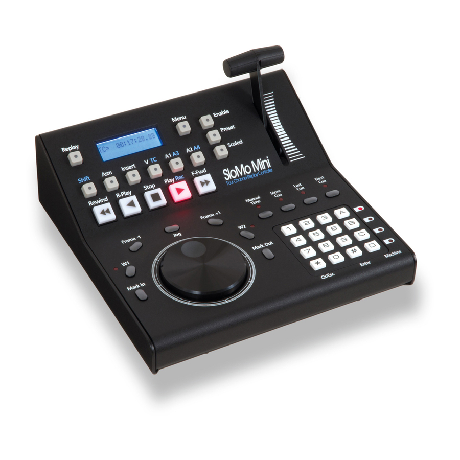
SloMo Mini User Manual Introduction The SloMo Mini is a compact controller for News, Sports, Scoreboard and other slow motion editing operations. It makes the operation of professional video recorders quick and easy. It’s a full-featured 4-machine editor and universal Jog remote for most VTRs and disk based recorders. -
Page 6: Features
Mark In and Mark Out keys to quickly store cue points • Capacity to store 1000 cue points or 400 in and out points with varispeed • Ability to transfer cues to/from another SloMo Mini or computer for backup or • editing Ability to import/export cues from/to Ash Vale SM-2a •... -
Page 7: Connecting
9-12 volts DC. The connector is a 2.1mm coaxial power connector. The center pin is positive. A power switch on the rear panel turns the SloMo Mini on or off. -
Page 8: Initialization
SloMo Mini User Manual Initialization The SloMo Mini configuration and T-Bar calibration can be reset by holding the SHIFT button while applying power to the SloMo Mini. After doing so, the display will show: Memory Initialized Then the display will show:... -
Page 9: Timecode Display
SloMo Mini User Manual Timecode Display When the SloMo Mini displays timecode, it displays more than just the current timecode. The character to the left of the hours field indicates drop frame operation. If the machine returns nondrop frame timecode, the SloMo Mini displays a space as shown in the screenshots below. - Page 10 SloMo Mini User Manual The character between the seconds and frames numbers indicates field 1 or 2. If the machine returns field 1 in the timecode, the SloMo Mini displays a period as in the screenshots below. TC= 02:35:52.18 Timecode display in Instant Replay and Cue and Park Modes indicating field 1...
-
Page 11: Buttons And Controls
SloMo Mini User Manual Buttons and Controls The following section introduces the controls on the SloMo Mini and details the functions of those controls. System Functions Menu Pressing this button causes the SloMo Mini to enter the configuration menu system. The Enter button is used to switch between the menu item and its parameters. -
Page 12: Transport Functions
See the Instant Replay section for more detail. Rewind Pressing either of these buttons causes the SloMo Mini to send the Rewind or Fast Forward command. It's action can be latching or momentary. The default action is latching. This can be configured in the menu. -
Page 13: Track Arming Functions
SloMo Mini User Manual Frame-1, Frame +1 Pressing either of these buttons causes the SloMo Mini to move the video device forward or backwards by one frame. The frame rate must be configured or the SloMo Mini to properly handle the transition around 00 sec. -
Page 14: T-Bar Functions
Refer to the T-Bar Operation section for more detail. This illuminates when the T-Bar is enabled. Preset Pressing this button causes the SloMo Mini to send the preset T-Bar speed command. The speed is configured in the configuration menu. Refer to the T-Bar Operation section for more detail. -
Page 15: Cueing Functions
In and Mark Out points for Cue/Clip Store functions. This illuminates to indicate that the Mark In and Mark Out points have been defined are waiting to be stored. The SloMo Mini is waiting for the user to press the Enter or CLR/ESC button. - Page 16 Enter or CLR/ESC button. Refer to the Cue Operations section for more detail. Enter Pressing this button causes the SloMo Mini to act on the pending operation. In Manual Time entry, it causes the SoMo Mini to command the video device to locate to the manually entered timecode, if it is valid and exists.
-
Page 17: Configuration Menu
SloMo Mini User Manual Configuration Menu There are a number of user configurable items that should be checked and set for your application. To go to the menu, press the MENU button. Select the menu item by turning the jog wheel. -
Page 18: Parameters
The defaults after initialization are shown in boldface. Parameters Time Code Type This is only used by the Step Frame (Frame+1 and Frame-1) functions. This determines how the SloMo Mini behaves at whole second boundaries. • • 30 drop •... - Page 19 1/16x • 1/2x • 3/32x • 3/4x T-Bar Message This sets the type of command sent by SloMo Mini during T-Bar operations • Jog Msgs • Variable Msgs • Shuttle Msgs Stop --> T-Bar This determines if pressing the STOP, PLAY, R-PLAY, REW or FFWD button will disable the T-Bar and turn off ENABLE LED.
- Page 20 SloMo Mini User Manual • Turns Off Step Frame This determines what will happen when a Frame+1 or Frame-1 button is pushed. • GoTo Mode This will issue a GoTo to the proper frame. This should be used with most "modern"...
- Page 21 Trk Data Tally Allows disabling of this tally, which, under unusual circumstances, might disrupt normal track select operations. If this is disabled, the SloMo Mini will not "know" of any track operation done on the controlled SloMo Mini itself. •...
- Page 22 Cues are only defined a start time. When a cue is recalled, a CueUp message is sent to SloMo Mini and no further action is taken. Cue start times are captured using the Store Cue button. This mode allows 1000 cues.
-
Page 23: Commands
You must be in Cue/Play/Stop or CuePlyStp Slo modes for this operation to take place! After each cue is played, the controlled SloMo Mini will stop for a period set by the Cue Delay Time, and then proceed to the next cue. - Page 24 When attaching to a computer, as RS-422A port or RS-422A to RS-232 converter is necessary. When the SloMo Mini is in Cue and Park mode, the data format conforms to the Ash Vale SM-2a protocol. When the SloMo Mini is in Cue/Ply/Stop or CuePlyStopSloMo mode, the data format is unique to the SloMo Mini.
-
Page 25: Initialization
SloMo Mini User Manual Initialization Init for Sports Pressing the ENTER key will set up parameters for typical sports slow motion operation. • Frame rate and type = 30 drop • Stop button sends Stop • Record Enabled • Latched FF and Rew •... -
Page 26: T-Bar Operation
SloMo Mini User Manual T-Bar Operation The T-Bar may be set via "T-Bar Range" to Normal, ±5%, ±10%, or bidirectional operation. Note: Due to limitations of the P2 protocol, these speeds may not be exact. Normal There are three main aspects of the "Normal" speed operation of the T-... -
Page 27: 5% Play Range
SloMo Mini User Manual When the ENABLE LED is off, movement of the T Bar will display (for about 1/2 second) the speed that would be sent were the T Bar enabled. This includes any min/max scaling if the T1 LED is lit. By this means, the operator can go to an exact speed position at any time without causing the controlled machine to move. -
Page 28: Cue Operations
SloMo Mini User Manual Cue Operations There is nonvolatile storage on the SloMo Mini for 1000 cues or 400 clips. These are numbered 000 – 999 or 000 - 399. The various operations involving cues are as follows: Basic Cue Operations To Goto a Predefined Cue #... -
Page 29: Cue And Park" Specific Operations
SloMo Mini User Manual “Cue and Park" Specific Operations To Manually Enter a Goto Time 1. Press ManTime button. The display will show: Enter Time --:--:--:-- 2. Start pressing numbers: they will scroll from right to left across screen. At any time, a first press of the CLR/ESC button will clear whatever entry is being... -
Page 30: To Copy A Time From One Cue To Another
2. Enter the desired Cue number on the numeric keypad. 3. Press ENTER. 4. Controlled SloMo Mini will be directed to cue to the Start time minus any preroll time. Once there, either a Play or a SloMo command will be issued. -
Page 31: Editing The Cue List
SloMo Mini User Manual When the SloMo Mini has reached the prestored Stop point, a Stop command is issued. Editing the Cue List It is possible to step thru the list of Cues and Enable or Disable them individually for inclusion in the "Play all Clips" playback. -
Page 32: Instant Replay
When the Replay button is pressed the following occurs: The SloMo Mini commands the video recorder to stop its current operation. • The SloMo Mini commands the recorder to cue back to a defined moment of • interest. When the recorder is at the moment of interest, the SloMo Mini commands the •... -
Page 33: Types Of Instant Replay
Typically, this will cause a new file to be created. Please keep in mind that the video recorder must stop recording video to playback video. This is a limitation of the video recorder, not the SloMo Mini. -
Page 34: Configuring A Video Recorder For Instant Replay
Aja Ki Pro Series This includes the Ki Pro, Ki Pro Rack and Ki Pro Quad. For the Ki Pro to respond to the SloMo Mini, RS-422 Remote Control on the Ki Pro must be enabled. 1. On the front panel of the Ki Pro, press the CONFIG button. -
Page 35: Videodevices Pix Series
VideoDevices PIX Series This includes the PIX-270i, PIX-260i and PIX-250i. For the PIX recorders to respond to the SloMo Mini, RS-422 Remote Control on the PIX recorders must be enabled. 1. On the front panel of the PIX recorder, press the MENU button. -
Page 36: Record Modes
SloMo Mini User Manual Record Modes The SloMo Mini includes buttons dedicated to adjusting the Edit Preset status of a target machine. The main modes are: Crash Recording Insure that neither the INS nor ASM LEDs are on. Holding down the Shift button, then pushing the PLAY button will place the machine(s) in the Crash Record mode. -
Page 37: Machine Control
Pressing a single button will switch both the output of the SloMo Mini and the tally back to it to the selected machine. If more than one button are held down, all SloMo Minis will receive commands from the SloMo Mini. -
Page 38: Gangway16 Or Gangway32 Operation
Setup To use the Gangway16 or Gangway32 with the SloMo Mini: 1. Connect port 1 of the SloMo Mini to the rear panel controller port of the Gangway16 or Gangway32 as shown below. 2. Enable Gangway Operation in the SloMo Mini menu as shown below. -
Page 39: Gangway16 Or Gangway32 Controls
16 ports. Tally Pressing this button allows you to select the port, which provides Tally information (timecode, status) to the SloMo Mini. In this mode, the Tally LED will illuminate and the VFD will show the Gangway16 or Gangway32 Tally routing. -
Page 40: Controlling The Gangway16 Or Gangway32
In addition, the Gangway16 or Gangway32 will illuminate buttons 1 and 6. This indicates that Ports 1 and 6 are enabled for output that is, commands from the SloMo Mini will be sent to video devices connected to Ports 1 & 6. - Page 41 The down pointing arrow will indicate the port that is configured as the Tally port or the port that the SloMo Mini listens to for Timecode and Status responses. As with the Enable function, to enable a port on the Gangway for Tally, make sure that the Tally LED is illuminated then, key in the 2 digit entry on the numeric keypad for the port.
-
Page 42: Appendix
JLCooper may provide this software at some point in the future, depending on demand. Contact the factory for details. For details on how to connect your SloMo Mini to a computer, refer to the pinout section. -
Page 43: Clip Transfer Protocol
SloMo Mini User Manual Clip Transfer Protocol The SloMo Mini can transfer cue information in one of two protocols: • Ash Vale SM-2a • SloMo Mini The SM-2a protocol is: The port settings are: 38400 bits/sec, no parity, 8 data bits, 1 stop bit. - Page 44 ⎟ ⎝ ⎠ These are the same values sent from the SloMo Mini to a machine and are defined on page 17 of the Sony document Protocol of Remote (9-pin) Connector 2nd Edition. The ‘@’ character terminates the sending of cue data.
-
Page 45: Pinout
Note: Some video devices do not use pin 1 for ground so you may have to connect pin 1 at each end of the SloMo Mini cable to pins 4 and 6 on your video device. The data transmission from the SloMo Mini follows the standard P2 specification. -
Page 46: Power
SloMo Mini on or off. The SloMo Mini comes with a power supply appropriate for the country in which the SloMo Mini was sold. If you need a power supply specific to your location, please contact your local distributor or JLCooper Electronics. -
Page 47: Caring For Your Slomo Mini
Troubleshooting If for some reason the SloMo Mini does not give you the expected results, take a moment to do some investigating. The most important concept is that you have your SloMo Mini connected properly as outlined in Installation and Use. -
Page 48: Jlcooper Electronics Limited Warranty
SloMo Mini User Manual JLCooper Electronics Limited Warranty JLCooper Electronics ("JLCooper") warrants this product to be free of defects in materials or workmanship for a period of 12 months from the date of purchase. This warranty is non-transferable and the benefits apply only to the original owner. Proof of purchase in the form of an itemized sales receipt is required for warranty coverage.
Need help?
Do you have a question about the SloMo Mini and is the answer not in the manual?
Questions and answers