Table of Contents
Advertisement
Quick Links
CAST IRON STOVE AND DIRECT-VENT
(FREESTANDING FIREPLACE HEATER)
OWNER'S OPERATION AND INSTALLATION MANUAL
NATURAL GAS BURNER SYSTEM MODEL MSDVBN,
PROPANE/LP GAS BURNER SYSTEM MODEL MSDVBP
IMPORTANT: This direct-vent burner system must be installed into approved cast iron stove
bodies, models MC(*) series ONLY. See page 3 of this manual.
WARNING: If the information in this manual is
not followed exactly, a fire or explosion may
result causing property damage, personal in-
jury, or loss of life.
FOR YOUR SAFETY
Do not store or use gasoline or other flammable
vapors and liquids in the vicinity of this or any
other appliance.
FOR YOUR SAFETY
WHAT TO DO IF YOU SMELL GAS
• Do not try to light any appliance.
• Do not touch any electrical switch
• Do not use any phone in your building.
• Immediately call your gas supplier from a
neighbor's phone. Follow the gas supplier's
instructions.
• If you cannot reach your gas supplier, call the
fire department.
This appliance may be installed in an aftermarket* manufactured (mobile) home, where
not prohibited by state or local codes.
*Aftermarket: Completion of sale, not for purpose of resale, from the manufacturer.
BURNER SYSTEM
REMOTE READY
Save this manual for future reference.
* Indicates Color Suffix Designation
WARNING: Improper installation,
adjustment, alteration, service, or
maintenance can cause injury or
property damage. Refer to this
manual for correct installation and
operational procedures. For as-
sistance or additional information
consult a qualified installer, ser-
vice agency, or the gas supplier.
— Installation and service must
be performed by a qualified in-
staller, service agency, or the gas
supplier.
— This appliance is only for use
with the type of gas indicated on
the rating plate. This appliance is
not convertible for use with other
gases, unless a certified kit is used.
Advertisement
Table of Contents

Summary of Contents for sun valley MSDVBP
- Page 1 BURNER SYSTEM OWNER’S OPERATION AND INSTALLATION MANUAL NATURAL GAS BURNER SYSTEM MODEL MSDVBN, PROPANE/LP GAS BURNER SYSTEM MODEL MSDVBP REMOTE READY IMPORTANT: This direct-vent burner system must be installed into approved cast iron stove bodies, models MC(*) series ONLY. See page 3 of this manual.
-
Page 2: Safety Information
SUN VALLEY STOVE COMPANY CAST IRON STOVE AND BURNER SYSTEM SAFETY This appliance is only for use with the 10. Have venting system inspected annu- type of gas indicated on the rating plate. ally by a qualified service person. If... -
Page 3: Product Identification
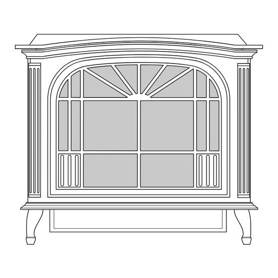
Grate Assembly the vent system and protect it from weather. Figure 1 - Sun Valley Direct-Vent Burner System Shown Installed in Approved Sun - A metal box that Vinyl Siding Standoff Valley Cast Iron Stove Body Models MC Series Only separates the vent cap from vinyl siding. -
Page 4: Pre-Installation Preparation
REQUIREMENTS to combustibles Determine the safest and most efficient lo- cation for your Sun Valley cast iron stove. Make sure that rafters and wall studs are not in the way of the venting system. Choose a location where the heat output is not af- 36"... -
Page 5: Cast Iron Stove And Direct-Vent Burner System Assembly
OWNER’S MANUAL PRE-INSTALLATION CAST IRON STOVE Carefully lay stove body on back to attach bottom components to stove body (see PREPARATION AND DIRECT-VENT Figure 7). Rest stove on drop cloth or blan- ket to avoid scratching stove edges. Continued BURNER SYSTEM Remove remaining pallet wood at- ASSEMBLY tached to bottom of stove body (see... - Page 6 SUN VALLEY STOVE COMPANY CAST IRON STOVE AND BURNER SYSTEM CAST IRON STOVE 10. Attach stove door by inserting step bolt 13. Carefully lift stove back up on its four through door hinge pivot hole and into attached legs. AND DIRECT-VENT threaded hole in stove body (see Figure 14.
- Page 7 OWNER’S MANUAL CAST IRON STOVE INSTALLING DIRECT-VENT INSTALLING OPTIONAL BURNER SYSTEM INTO BLOWER ACCESSORY AND DIRECT-VENT STOVE BODY BURNER SYSTEM NOTICE: If installing blower in an Attach the two brackets to the back of existing stove burner system with ASSEMBLY the stove (see Figure 17).
- Page 8 SUN VALLEY STOVE COMPANY CAST IRON STOVE AND BURNER SYSTEM CAST IRON STOVE 3. Place speed control on left inside of rear 7. Peel off the backing paper and stick the cover and push the plastic control shaft supplied wiring diagram decal on the AND DIRECT-VENT through opening (see Figure 19).
-
Page 9: General Venting
Lift rear panel over vent pipe connection • Only use Sun Valley or Simpson Dura- • There must not be any obstruction such on burner system. Rear cover will rest on... - Page 10 SUN VALLEY STOVE COMPANY CAST IRON STOVE AND BURNER SYSTEM GENERAL VENTING Continued Fixed Openable Fixed Closed Closed Openable TERMINATION CAP GAS METER RESTRICTED AREA AIR SUPPLY INLET (TERMINATION PROHIBITED) A = clearance above grade, veranda, porch, deck, or balcony...
-
Page 11: Venting Installation
OWNER’S MANUAL VENTING • Installation of any component part not roofline. You may use one or two 90° elbows manufactured or approved by DESA in this vent configuration. See Vertical Ter- INSTALLATION International mination Configurations on pages 17 and 18. •... -
Page 12: Installation
SUN VALLEY STOVE COMPANY CAST IRON STOVE AND BURNER SYSTEM VENTING Snorkel INSTALLATION Continued INSTALLATION FOR HORIZONTAL TERMINATION 1. Determine the route your horizontal venting will take. Note: The location 12" Minimum of the horizontal vent termination on the exterior wall must meet all local and national building codes and must not be easily blocked or obstructed. - Page 13 OWNER’S MANUAL VENTING 4. Apply a bead of non-hardening mastic Carefully move the stove with vent as- around the outside edge of the vent cap. sembly attached toward the wall and INSTALLATION Position the vent cap in the center of insert the vent pipe into the horizontal the 7 "...
- Page 14 SUN VALLEY STOVE COMPANY CAST IRON STOVE AND BURNER SYSTEM VENTING Horizontal Venting Vertical (V) Horizontal (H) INSTALLATION 60" min. 28" max. Continued 72" min. 48" max. 84" min. 72" max. Horizontal Termination Configu- 96" min. 10' max. rations Figures 29 through Figure 31 show differ-...
-
Page 15: Installation For Vertical Termination
OWNER’S MANUAL VENTING INSTALLATION Continued Venting with Two 90° Elbows Vertical (V) Horizontal (H Horizontal (H 6' min. 4' max. 7' min. 6' max. 8' min. 10' max. 20' max. 12' max. Figure 31 - Horizontal Termination Configuration for Rigid Venting Using Two 90 ° Elbows with Termination at 90 ° with Stove INSTALLATION FOR 2. - Page 16 SUN VALLEY STOVE COMPANY CAST IRON STOVE AND BURNER SYSTEM VENTING Level 6. Continue to add pipe sections until the height of the vent cap meets the mini- Cathedral ceiling INSTALLATION mum building code requirements de- support box scribed in Figure 21 on page 10. Note :...
- Page 17 OWNER’S MANUAL VENTING Venting with Two 90° Elbows Vertical (V) Horizontal (H INSTALLATION Horizontal (H Continued 5' min. 2' max. Note: Install 6' min. 4' max. Vertical Termination restrictor into 4" 7' min. 6' max. Configurations collar of burner 8' min. 8' max.
-
Page 18: High Altitude Installation
D1020BK 7" x 48" Black Coaxial Pipe (1 pk) 945B 7" x 45° Elbow Your Sun Valley cast iron stove and direct- D1030BK 7" Adjustable (7-12") Black Vinyl Siding Standoff vent burner system has been AGA tested Coaxial Pipe (1 pk) -
Page 19: Stove And Direct-Vent Burner System Installation
OWNER’S MANUAL STOVE AND For propane/LP connections only, the in- CAUTION: Use pipe joint seal- staller must supply an external regulator. DIRECT-VENT ant that is resistant to liquid pe- The external regulator will reduce incoming troleum (LP) gas. gas pressure. You must reduce incoming BURNER SYSTEM gas pressure to between 11 and 14 inches of We recommend that you install a sediment... -
Page 20: Checking Gas Connections
SUN VALLEY STOVE COMPANY CAST IRON STOVE AND BURNER SYSTEM STOVE AND CHECKING GAS CONNECTIONS DIRECT-VENT BURNER SYSTEM WARNING: Test all gas pip- ing and connections for leaks INSTALLATION after installing or servicing. Cor- Continued rect all leaks at once. - Page 21 OWNER’S MANUAL STOVE AND Open POSITION Manual DIRECT-VENT Shutoff Valve BURNER SYSTEM INSTALLATION Closed POSITION Continued Figure 43 - Manual Shutoff Valve Test Pressures Equal To or Less Than Manual Shutoff Valve 1/2 PSIG (3.5 kPa) 1. Close manual shutoff valve (see Fig- ure 43).
- Page 22 SUN VALLEY STOVE COMPANY CAST IRON STOVE AND BURNER SYSTEM STOVE AND Gently remove the cover of the ther- Feed wires through mostat from the base. Grasp the sides rectangular slots DIRECT-VENT of the cover firmly and pull to separate from the base.
- Page 23 OWNER’S MANUAL STOVE AND Remove the screws from the 2 tabs at the top of the glass door while holding DIRECT-VENT door securely keeping it from falling forward (see Figure 54). BURNER SYSTEM Grasp door by both sides and ease it INSTALLATION upward off of the lower bracket (see Figure 54).
- Page 24 SUN VALLEY STOVE COMPANY CAST IRON STOVE AND BURNER SYSTEM STOVE AND the rear log as shown in Figure 57. See Figure 58. Place log #4 (small log) onto the front Lava rock may be placed along sides DIRECT-VENT left part of the grate making sure the and front inside burner system bottom.
-
Page 25: Operating Stove With Burner System
OWNER’S MANUAL OPERATING STOVE LIGHTING TO TURN OFF GAS INSTRUCTIONS TO APPLIANCE WITH BURNER Open lower louver panel. 1. STOP! Read the safety information SYSTEM in column one. 2a. Turn ON/OFF switch to “OFF”. 2. Open lower panel. 2b. If Using Optional Hand-Held Re- FOR YOUR SAFETY mote: Set selector switch in the OFF 3. -
Page 26: Optional Remote Operation
SUN VALLEY STOVE COMPANY CAST IRON STOVE AND BURNER SYSTEM OPERATING STOVE Selector Switch in • In auto mode, the room temperature Gas Control Remote Position is controlled by the thermostat in the Knob in On WITH BURNER (Optional Remote Position hand-held remote control unit. -
Page 27: Inspecting Burners
OWNER’S MANUAL OPERATING STOVE BURNER FLAME PATTERN Upon installation, the thermostat must be allowed to stabilize at room tempera- WITH BURNER Burner flames will be steady; not lifting or ture for a minimum of 30 minutes for floating. Flame patterns will be different proper operation. -
Page 28: Cleaning And Maintenance
SUN VALLEY STOVE COMPANY CAST IRON STOVE AND BURNER SYSTEM CLEANING AND LOGS WARNING: Only parts sup- • If you remove logs for cleaning, refer to MAINTENANCE plied by the manufacturer should Installing Logs, Lava Rock, and Glowing be used when replacing broken Embers, page 24, to properly replace logs. -
Page 29: Troubleshooting
OWNER’S MANUAL TROUBLESHOOTING WARNING: Turn off burner CAUTION: Never use a wire, system and let cool before ser- needle, or similar object to clean Note: For additional help, visit DESA vicing. Only a qualified service pilot. This can damage pilot unit. International’s technical service web person should service and repair site at www.desatech.com. - Page 30 SUN VALLEY STOVE COMPANY CAST IRON STOVE AND BURNER SYSTEM TROUBLESHOOTING Continued OBSERVED PROBLEM POSSIBLE CAUSE REMEDY Burner does not light after pilot is lit 1. Burner orifice clogged 1. Clean burner (see Cleaning and Maintenance, page 28) or replace burner orifice 2.
- Page 31 OWNER’S MANUAL TROUBLESHOOTING Continued WARNING: If you smell gas • Shut off gas supply. • Do not try to light any appliance. • Do not touch any electrical switch; do not use any phone in your building. • Immediately call your gas supplier from a neighbor’s phone. Follow the gas supplier’s instructions.
-
Page 32: Replacement Parts
SUN VALLEY STOVE COMPANY CAST IRON STOVE AND BURNER SYSTEM REPLACEMENT WIRING DIAGRAM PARTS CAUTION: Label all wires prior Note: Use only original replacement parts. to disconnection when servicing This will protect your warranty coverage for controls. Wiring errors can cause parts replaced under warranty. -
Page 33: Specifications
70 lbs/31.8 kg Shipping 75 lbs/34 kg 75 lbs/34 kg * When installed in Sun Valley cast iron stove body (MC Series). ACCESSORIES Purchase these stove and burner system accessories from your local dealer. If they can not supply these accessories, call Sun... -
Page 34: Illustrated Parts Breakdown
SUN VALLEY STOVE COMPANY CAST IRON STOVE AND BURNER SYSTEM ILLUSTRATED PARTS BREAKDOWN MSDVBN MSDVBP 26-3 26-1 26-4 26-2 106021... -
Page 35: Parts List
OWNER’S MANUAL PARTS LIST This list contains replaceable parts used in your burner system. When ordering parts, follow the instructions listed under Replacement Parts on page 32 of this manual. MSDVBN MSDVBP PART NUMBER DESCRIPTION QTY. 105478-01BR Firebox Assembly M11084-26... - Page 36 SUN VALLEY STOVE COMPANY CAST IRON STOVE AND BURNER SYSTEM ILLUSTRATED PARTS BREAKDOWN SUN VALLEY STOVE MC(*) SERIES (* Indicates Color Suffix Designation) (Discarded During Assembly) 106021...
- Page 37 OWNER’S MANUAL PARTS LIST This list contains replaceable parts used in your stove. When ordering parts, follow the instructions listed under Replacement Parts on page 32 of this manual. SUN VALLEY STOVE MC(*) SERIES (* Indicates Color Suffix Designation) PART DESCRIPTION QTY.
-
Page 38: Warranty Information
This warranty gives you specific legal rights, and you may also have other rights that vary from state to state. For information about this warranty write: Sun Valley Stove Company INTERNATIONAL Div.
Need help?
Do you have a question about the MSDVBP and is the answer not in the manual?
Questions and answers