Table of Contents
Advertisement
Quick Links
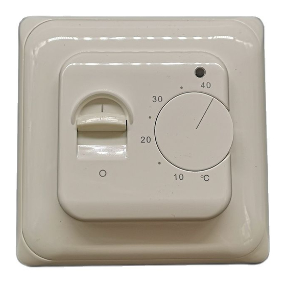
RTC70.XX Electronic Heating Thermostat
RTC70.XX electronic heating thermostat
This type electronic thermostat for mounting in standard wall box,
the thermostat is adjustable to required temperature from +5/+40C,
the LED shows that the heat is On, the thermostat is recommended
for control of electric heating devices or on/off valve actuator used
in water-based heating systems
Selection Table
Model
Current
Sensor
RTC70.13
3A
built-in sensor
RTC70.16
16A
built-in sensor
RTC70.26
16A
floor sensor
Technical data:
Voltage
: AC230V(AC110V / AC24V available)
Power consumption
: 5W
Setting range
: 5
Switching differential
:
Ambient temperature
: -5
Protective housing
: IP20
Housing material
: anti-flammable PC
Floor sensor
:
rubber-thermoplastic
cable length is 3m
Dimension:
.
30
.
20
Mounting of Floor Sensor
Floor sensor should be placed in installation pipe which is embed-
ded in floor, the pipe is thickened in the end and placed as high as
possible in the concrete layer. Sensor cable may be extended up to
50 m with separate cable f or power current. Two conductors in a
multi-conducting cable, which e.g. is used for supply of heating
cable, may not be used. Voltage signals, which may disturb the
function of the thermostat, may occur. If the cable is used with screen,
the screen may not be connected to the ground, but must be
connected to terminal 7, the best installation is attained with a
separate cable for the sensor, which is then mounted in a separate
conduit.
Temperature and Value of Floor Sensor
Temperature ( )
5
10
20
30
40
Application
for control of on/off electric or
electro-thermal actuator
for
control of electric heating devices
40
0.5K
50
NTC sensor,
40
Value ( )
22070
17960
12091
8312
5827
Placement of Thermostat
Thermostat is to be mounted on the wall with free air circulation
around it . Furthermore it has to be placed where it is not
influenced by any other heating sources (e.g. the sun), draft from
doors or windows, or by the temperature of an exterior wall.
Operation manual
On/Off
-On
-Off
Temperature setting
5
40
Indicator
the light is red when heat
is on
Temperature Setting
Thermostat has a scale range of +5/+40 . To assist the adjust-
ment, the thermostat has a LED which will glow RED when the
heating is ON. The thermostat should be set to maximum tem-
perature setting until the desired temperature of the room or
floor is achieved. The control knob should then be turned back
until the LED goes out. Fine adjustments can be made over the
next 1/2 days to suit individual requirements.
Thermostat Adjustment
When the room temperature has been stabilized, the thermos-
tat set position may be adjusted to match actual room tempera-
ture. Measure the temperature of the room with an accurate
thermometer. Remove control knob(1) and spin the pole(D),
then reposition the control knob so that the indicated tempera-
ture line shows the same as the measured temperature
(picture 2). We have adjusted the temperature, please do not
spin the pole when installation.
Max./Min. Temperature Setting
A locking mechanism is positioned behind the control knob to
limit the amount of adjustment possible. By loosening the little
screw C (picture2)the scale range can be locked, e.g. Between
20
and 25 . The red ring indicates the maximum tempera-
ture and the green ring indicates the minimum temperature.
Advertisement
Table of Contents

Related Manuals for HVAC Controls RTC70.XX


Summary of Contents for HVAC Controls RTC70.XX
- Page 1 Mounting Instructions RTC70.XX Electronic Heating Thermostat RTC70.XX electronic heating thermostat Placement of Thermostat This type electronic thermostat for mounting in standard wall box, Thermostat is to be mounted on the wall with free air circulation the thermostat is adjustable to required temperature from +5/+40C, around it .
- Page 2 Mounting Instructions RTC70.XX Electronic Heating Thermostat Mounting steps: RTC70.13 Imax=3A RTC70.16 Imax=16A Sensor RTC70.26 Imax=16A RTC70.22 Imax=20A Parts Knob Cover Thermostat External frame Internal frame...
Need help?
Do you have a question about the RTC70.XX and is the answer not in the manual?
Questions and answers