Table of Contents
Advertisement
Advertisement
Table of Contents

Summary of Contents for Lodam LMC 320
- Page 1 User Manual Heat Pump Controller LMC 320 Lodam Heat Pump Controller...
-
Page 3: Table Of Contents
C o n t e n t 1. Read this first! Reading instructions User manual Safety 2. General 3. Definitions 4. Overview of the LMC320 Heat Pump Controller 5. How to ... Use the display and the menu system Show User information Display actual measured temperatures Set hot water temperature Set room temperature for heating... - Page 4 Defrost handling Safety cut out Sensor monitoring Hot side pump control Cold pump control Aux pump control Pump exercise function Freeze protection Minimum evaporator/brine temperature limiter 7. Menu system Overview of the menu system Main menu Password menu User menu User - Display menu User- Alarm menu User - Time setting menu...
- Page 5 10. Technical data 11. I/O list for the LMC320 Heat Pump Controller 12. Drawings LMC300 LUP200 Panel cutout 13. Standards 14. Alarm system and trouble shooting Alarm list 15. Network 16. Firmware update 17. Accessories 18. Ambient compensation curves 19. NTC temperature/resistance table 20.
-
Page 7: Read This First
1. Read this first! The contents of this manual are subject to change without notice. Lodam electronics holds the copyright to this user’s manual. The user shall follow any instructions given in this user manual entirely and not only partly. Any non-following of this user manual result in exclusion of all warranties, guarantees, and liabilities. -
Page 8: User Manual
U se r Manual - Lodam Heat Pump Controller Danger!! General danger. Danger!! High voltage. Danger of electrical current or voltage. Reading Text listed as Installer.Service, references to an entry in the menu system, please see the full menu system in Menu system. -
Page 9: General
Our Lodam Heat Pump Controller is designed for most heat pump applications. The LMC320 Lodam Heat Pump controller can be used in most heat pump applications to obtain highest possible COP. • Ground - Brine / Water Heat Pumps •... -
Page 10: Definitions
Hardware/electronics Input / Output (electrical signals in and out of a unit) Limiter Shortform for a limiting function which monitors the operating conditions Lodam Multi Tool (PC communication tool for Lodams controllers) Normally Closed (relay) Normally Open (relay) Pdis Discharge pressure... -
Page 11: Overview Of The Lmc320 Heat Pump Controller
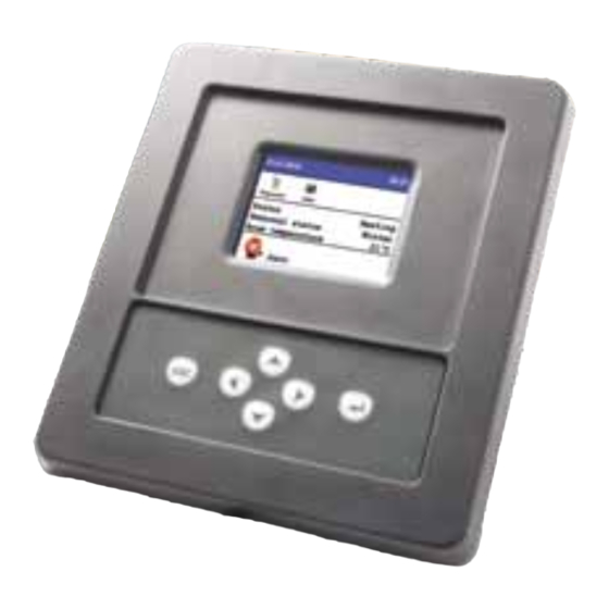
4. Overview of the LMC320 Heat Pump Controller Display LUP200 Ethernet Connection(option) Power supply 24 VAC Heating supply temperature Compressor Heating return temperature Heater Water tank temperature Hot tap water Ambient temperature Cold pump Room temperature Hot side pump Heating tank temperature Solar panel pump Cold side supply temperature Aux circulation pump... -
Page 12: How To
U ser Manual - Lodam Heat Pump Controller 5. How to ... Use the display and the menu system The buttons on the user panel have the following functions: Esc button Cancel editing of a setting / Return to higher level... -
Page 13: Show User Information
Show User information The following menu is the main menu and the default. The user panel returns to this after 10 min without user activity. 31-01-2010 09:31 Password User Status Heating Seasonal status Winter Room temperature 21°C Alarm From the main menu, press the Right arrow to highlight the User icon and press the Enter button to show the User menu User 31-01-2010... -
Page 14: Display Actual Measured Temperatures
U ser Manual - Lodam Heat Pump Controller Display actual measured temperatures Show the user information as listed above and use the Down arrow to highlight the Display menu line. Press the Enter button to show the Display menu with measured temperatures and status. -
Page 15: Set Room Temperature For Heating
Set room temperature for heating Open the User menu and scroll to the Room temp. set point with the Up or Down arrows. Press the Enter button to enter editing mode and adjust the temperature of the Room temperature set point to the desired temperature. - Page 16 U ser Manual - Lodam Heat Pump Controller Press the Enter button to start editing mode and enter the correct password with use of the up and down arrows. Press the Enter button to select it. Press the Esc button to return to main menu from where there now is...
-
Page 17: Set Control Mode For The Installation
Set control mode for the installation Open the Installer menu and scroll to the line with Service. Under Service menu open the sub menu Manual by pressing the Enter button. 31-01-2010 31-01-2010 Manual 09:31 09:31 MainSwitch RE1 - Compressor RE2 - Heater RE3 –... -
Page 18: Enable Use Of A Solar Panel
U ser Manual - Lodam Heat Pump Controller Defrost 31-01-2010 09:31 Defrost method Auto Ice level -2.0°C Relative ice level 7.0°C Ice time 20min Min time between defrost 60min Evaporator stop temp. 5.0°C Max defrost time 10min Advanced defrost settings >... - Page 19 In Hot water source select a setting which uses the solar panel: SP, HP+SP, SP+EH, HP+EH+SP, SP+HP-DUAL. Default setting is only to use the heat pump, HP. Settings for the solar panel can be set by opening the Solar panel settings menu Installer 31-01-2010...
-
Page 20: Functions Of The Lmc320
U ser Manual - Lodam Heat Pump Controller 6. Functions of the LMC320 The LMC320 controller is designed for heat pumps for domestic heating. The system contains an evaporator for cooling air or brine, a compressor with either fixed or variable speed and either a common or dual condensers for heating of water. -
Page 21: Heating Control - Min Comp
Heating control – Min comp. Compensation is disabled and setpoint for return water temperature is set to minimum allowed return water temperature. Heating control – Ambient Use the actual ambient temperature to calculate a needed setpoint. It is possible to pre-program the setpoint for the return water temperature with respect to the actual ambient temperature. -
Page 22: Heating Control - On/Off Room Temperature Control
U ser Manual - Lodam Heat Pump Controller temperature if the room temperature in the critical room can not be maintained with the calculated return water temperature setpoint form ambient compensation. Room compensation has two settings, first the wanted setpoint in... - Page 23 There are four modes of the heating control 1. On/Off compressor control based on return water temperature 2. Modulating compressor control based on supply water temperature 3. On/Off compressor control based on heating accumulator water tank temperature 4. Modulating compressor control based on heating accumulator water tank temperature –...
-
Page 24: Supplemental Heating
U ser Manual - Lodam Heat Pump Controller The first 5 second after start a constant preset voltage (Ustart) is sent to the inverter. After that a voltage linear to the capacity is sent to the output (see graph below). The rate of capacity change is limited to max 1% per second. -
Page 25: Hot Tap Water Valve
Hot tap water valve The output for the 3-way valve is inactive when the water temperature is within the setpoint – neutral zone setting. When there is a request for more hot water in the tank, the relay is activated whether the compressor or supplemental heating is used. -
Page 26: Safety Cut Out
U ser Manual - Lodam Heat Pump Controller frost at low ambient temperatures the LMC320 is equipped with an automatic defrost system. The defrost method can be Air, Hot gas, Auto or Off. Air means only the fan is used for melting the ice in the evaporator. Hot gas... -
Page 27: Aux Pump Control
to allow heat to be created. A low limit ambient temperature can be set and below this temperature the fan / brine pump will run continuously even if the heat pump is stopped. Default this setting is off. There is also a high limit ambient temperature for the fan / brine pump. -
Page 28: Menu System
U ser Manual - Lodam Heat Pump Controller 7. Menu system Overview of the menu system 31-01-2010 31-01-2010 Run time 09:31 09:31 Heat pump 217h Compressor 173h Heater Hot water Cold side pump 187h Hot side pump 200h Solar panel pump... -
Page 29: Main Menu
Main menu 31-01-2010 09:31 When the user – or installer password has been entered, the respective icon appears. By moving the cursor to the wanted icon and pressing Enter key, Password User Installer the submenus are shown. Status Heating Seasonal status Winter Room temperature 21°C... -
Page 30: User Menu
Us e r Manua l - Lodam Heat Pump Controller User menu User 31-01-2010 09:31 Language: Language English At the moment only English is available. Display > Display: Alarm > Time > View values from the unit Room temp. Set point 21.0°C... -
Page 31: User - Display Menu
User - Display menu Display 31-01-2010 09:31 View readings and settings for the heat pump. Heating Status Heating supply temp. 35.7°C Status: Heating return temp. 30.9°C Heating, Hot water, Off Water tank temp. 44.0°C Heating supply temp.: Ambient temp. 2.1°C Supply temperature for heating system. -
Page 32: User- Alarm Menu
Us e r Manua l - Lodam Heat Pump Controller User- Alarm menu Alarm 31-01-2010 09:31 Show active or unacknowledged alarm and W104: T3 Open – A WARNING warnings. Only alarms starting with a capital before the text Warning, Alarm or Critical can be acknowledged and will be cleared from the list. -
Page 33: Installer - Heat Pump Settings
Installer - Heat pump settings Heat pump 31-01-2010 09:31 Settings for controlling the heat pump. HP stop sensor Return Stop all sensor Supply HP stop sensor: HP stop temp 70.0 °C Control sensor to use for stopping the heat Stop all temp 70.0 °C pump at high temperature Control mode... -
Page 34: Installer - Hot Water Settings
Us e r Manua l - Lodam Heat Pump Controller Default: Ret On/Off Min comp stop time: Minimum off time for the compressor. Range 1 – 15 min Default 6 min. Electrical heat delay: Minimum wait time before the electrical supply heating is turned on. - Page 35 HP+SP SP+EH HP+EH+SP: All sources are used according to best energy efficiency SP+HP-DUAL Default: HP Hot water set point: Desired hot water temperature Range 5 ° to 55 °C Default 45 °C Hot water neutral zone: Neutral band from hot water setpoint. Range 0.1 to 15.0 °C Default 4.0 °C Hot water capacity:...
-
Page 36: Installer - Heating Settings
Us e r Manua l - Lodam Heat Pump Controller Installer - Heating settings Heating 31-01-2010 09:31 Setup of house heating control. Heating source HP+EL Heating controller > Heating source: Room/amb compensation > Different heat sources are selectable: 20.0°C Set point Min HP: Heat pump 55.0°C... -
Page 37: Installer - Heating Controller Menu
Installer - Heating controller menu Heating controller 31-01-2010 09:31 The settings in theis menu are only used when 10.0 % Stop capacity frequency inverter operation is used –modulating Start diffence cap. 10.0 % control. 2.0 V Voltage at 0% Setup of the heating controller. Voltage at 100% 10.0 V The heating control is a PI-regulator that calculates... -
Page 38: Installer - Ambient / Room Temperature Compensation Menu
Us e r Manua l - Lodam Heat Pump Controller Integration time: Integration time for the heating PI-regulator. Range 30 – 600 s Default 240 s Evaporator temp. min: Limit for limitation function. When the evaporator temperature is below this value, the capacity is reduced to avoid low pressure cut-out. - Page 39 Ambient curve: Select between 10 preconfigured curves or a manual configured curve Default curve 1 Curve -20°C: Corrected room temperature setpoint at ambient temperature of -20 °C Range -100.0 – 100.0 °C Default 45.0 °C (Curve 1) Curve -10°C: Corrected room temperature setpoint at ambient temperature of -10 °C Range -100.0 –...
-
Page 40: Installer - Defrost Settings
Us e r Manua l - Lodam Heat Pump Controller Installer - Defrost settings Defrost 31-01-2010 09:31 Settings for the automatic defrost of the evaporator Defrost method Auto in air evaporator systems. Not used for brine Ice level -2.0°C systems. -
Page 41: Installer - Advanced Defrost Settings Menu
Default 20 min Min time between defrost: Minimum time between two automatic defrosts. Range 10 – 480 min Default 60 min Evaporator stop temp.: Defrost stops when the evaporator temperature exceeds this setting. Only used for hotgas defrost. Range 1.0 – 25.0 °C Default 5.0 °C Max defrost time: Maximum allowable time for the evaporator... -
Page 42: Installer - Solar Panel Settings
Us e r Manua l - Lodam Heat Pump Controller Fast ice melt temp.: Tambient Defines the ambient temperature above which the ice timer is decremented fast when the compressor is switched off or when Force fan Ambient max the evaporator temperature is above 1 °C. - Page 43 Stop part: Scale of Start temp. diff used for stopping hot water production again. 0.0: stop at set point; 0.5: stop at ½ * Start temp. diff Range 0.0 – 1.0 Default 0.0 (Stop at setpoint) Max solar panel temp.: Max allowable solar panel temperature.
-
Page 44: Installer - Service Menu
Us e r Manua l - Lodam Heat Pump Controller Installer - Service menu Service 31-01-2010 09:31 Show software version, runtime counters and use LMC 320 v. manual mode for trouble shooting purposes. LUP 200 v. Counters > LMC 320 v.: Manual >... -
Page 45: Installer - Runtime Counters
Installer - Runtime counters 31-01-2010 31-01-2010 Run time 09:31 09:31 Hour counter or activation counters for different Heat pump 217h functions in the controller Compressor 173h Heater Hot water Cold side pump 187h Hot side pump 200h Solar panel pump Cold side pump low Aux circ pump 217h... - Page 46 Us e r Manua l - Lodam Heat Pump Controller RE4 – Cold pump: If set to On the relay for the cold pump is activated. RE5 – Hot pump: If set to On the relay for the hot water circulation pump is activated.
-
Page 47: Examples Of Application Use
8. Examples of application use LMC 320, Air to water, ON/OFF control, solar panel connected to hot water tank 7. oktober 2010 Air to water, compressor On/Off control, solar panel connected to hot water tank LMC 320, ground to water, no solar panel, heating tank on heating system 7. -
Page 48: Connections
U ser Manual - Lodam Heat Pump Controller 9. Connections Connections on the LMC300 LMC320 Heat Pump Controller LMC300 512 kB + LOM309 Supply 24V ac AO0 Compressor inverter 0-10V R1 Compressor R2 Heater T1 Heating supply temp. R3 3-way valve T2 Heating return temp. -
Page 49: Connection Between Lmc300 And Lup200
Connection between LMC300 and LUP200 LMC300 LUP200 RS485 12VU +12 VDC In Connections on the LUP200 Display Power RS485 heater supply Max. 1.5 A Remove jumper if external power supply is used Connections... -
Page 50: Technical Data
U ser Manual - Lodam Heat Pump Controller 10. Technical data LMC320 Heat Pump Controller with LOM309 Slave I/O Board Technical specifications, LMC320+LOM309: Size 175mm (l) * 100mm (w) Power supply 12VDC (Vbat); 15 - 30VDC/12 - 24VAC; 110 - 230 VAC +/- 10%, 50-60 HZ... - Page 51 Technical specifications, LUP200: Display 262k colors, graphical display 320x240 pixels PCB dimensions 85mm (l) * 60mm (w) * 20mm (h) Power supply 12V – 24VDC AT91SAM7, ARM7 processor Operating temperature -20˚C ~ + 60°C Storage temperature -30°C ~ + 60°C 16 MB RS485 ports 1 port with 2 x connections and possibility of connecting 4 units in “daisy chain”...
- Page 52 U ser Manual - Lodam Heat Pump Controller Technical specifications, LOM320: Size 92mm (w) * 78mm (h) Power supply 12 VDC ARM920T, 32bit, 200MHz Operating temperatures -20°C ~ +60°C Storage temperatures -30°C ~ +60°C Ethernet 1; 10/100 Mbit RS485 ports...
-
Page 53: I/O List For The Lmc320 Heat Pump Controller
3,3VDC, max 3,3mA, 1kΩ. Not galvanic isolated. Heating supply Temp1 Heating supply temperature temperature Lodam NTC sensor Measurement range: -60°C to 130°C Accuracy: • ±1°C in the range -30°C to 60°C • ± 3°C in the range -60°C to -30 °C •... - Page 54 U ser Manual - Lodam Heat Pump Controller Name Type Logic Description Water tank temperature Temp3 Water tank temperature Lodam NTC sensor Measurement range: -60°C to 130°C Accuracy: • ±1°C in the range -30°C to 60°C • ± 3°C in the range -60°C to -30 °C •...
- Page 55 Type Logic Description Cold side return Temp8 Cold side return temperature temperature Lodam NTC sensor Measurement range: -60°C to 130°C Accuracy: • ±1°C in the range -30°C to 60°C • ± 3°C in the range -60°C to -30 °C •...
- Page 56 U ser Manual - Lodam Heat Pump Controller Name Type Logic Description Cold pump RE4OUT Relay for Cold pump ON Max 10A@250VAC/10A@30VDC Hot side pump RE5OUT Relay for Hot side pump ON (NC) Max 10A@250VAC/10A@30VDC Solar panel pump RE2OUT Relay for Solar panel pump ON...
-
Page 57: Drawings
12. Drawings All dimensions in mm. LMC300 Mounting dimensions. 175,0 ±0,5 79,7 85,3 ±0,1 ±0,1 ±0,2 4,5 0,1 Drawings... -
Page 58: Lup200
U ser Manual - Lodam Heat Pump Controller LUP200 24,5 ±1,0 135,0 ±1,0 11,0 ±0,5 PLATINUM Connectors Panel cutout 107,0 ±0,5 56,0 ±0,2 4,6 0,1 4x Max. R2,0 70,0 ±0,2 115,1 ±0,2 Drawings... -
Page 59: Standards
13. Standards • EN61000-6-1 (EMC, Immunity for residential, commercial and light- industrial environments). • EN61000-6-3 (EMC, Emission standard for residential, commercial and light-industrial environments). • EN60204-1 (Safety of machinery. Electrical equipment of machines. General requirements). Standards... -
Page 60: Alarm System And Trouble Shooting
U ser Manual - Lodam Heat Pump Controller 14. Alarm system and trouble shooting The LMC320 controller is equipped with a failure and alarm diagnoses system. There are three alarm levels: Warning, Alarm and Critical. A warning does not stop the unit but affects its temperature control precision. -
Page 61: Alarm List
Alarm list Alarm number Type Name Description Elimination Sensors Warning T1 Open Heating supply temperature Check cable and connectors open connection Warning T1 Short Heating supply temperature Check cable and connectors short-circuited Warning T2 Open Heating return temperature Check cable and connectors open connection Warning T2 Short... - Page 62 U ser Manual - Lodam Heat Pump Controller Type Name Description Elimination Alarm number Hardware Critical LOM9 LOM9 missing Check connection missing Operation Warning Hi Pres High pressure switch active The unit restarts when the pressure drops below high pressure switch low-limit again.
-
Page 63: Network
This will update the software in the LMC320 controller and the LUP200 display if necessary. 17. Accessories Lodam has the following NTC temperature sensors in stock for use with the LMC320 controller. In the table are the suggested variant to use and an alternative sensor. -
Page 64: Ambient Compensation Curves
U ser Manual - Lodam Heat Pump Controller 18. Ambient compensation curves The user can choose between 10 predefined curves and also adjust a user specific curve. A curve is used to calculate the reference setpoint for the return water temperature. -
Page 65: Ntc Temperature/Resistance Table
19. NTC temperature/resistance table Table with relation between temperature and measured resistance in the NTC sensor. Resistance is in Ω (Ohm) an temperature in °C. °C + 0 °C + 2 °C + 4 °C + 6 °C + 8 °C 667828 579718 504230... -
Page 66: Index
U ser Manual - Lodam Heat Pump Controller 20. Index Hot water settings Installer menu Accessories 62 Main menu Alarm list 60 Manuel mode Alarm system 59 Password menu Ambient compensation curves 63 Runtime counters Ambient / Room temp. compensation 20,37... -
Page 67: Notes
21. Notes Notes... - Page 68 Lodam electronics a/s Tel. +45 73 42 37 37 lodam@lodam.com Kærvej 77 Fax +45 73 42 37 30 www.lodam.com 6400 Sønderborg Denmark...
Need help?
Do you have a question about the LMC 320 and is the answer not in the manual?
Questions and answers