Table of Contents
Advertisement
Quick Links
Advertisement
Table of Contents

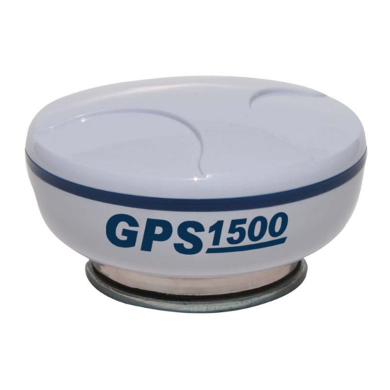
Summary of Contents for Ag Leader GPS 1500
- Page 1 GPS 1500 User Manual PN 2005906 Rev. E...
-
Page 3: Cable Connections
VERVIEW NTRODUCTION The GPS 1500 is a smart antenna that tracks GPS and SBAS (WAAS and EGNOS) signals. ABLE ONNECTIONS DISPLAY GPS O VERVIEW The receiver is preconfigured and will work out of the box for most applications. When powered for the first time, the reciever will perform a “cold start,”... -
Page 4: Differential Operation
The reciever will automatically scan and track satellite signals. This automatic tracking allows you to focus on other aspects of differential operation without the need to tune the receiver. The GPS 1500 features two-channel SBAS tracking that provides an enhanced ability to maintain a lock on a SBAS satellite when more than one satellite is in view. -
Page 5: Utility Setup
ROCEDURE The default GPS settings are 4800 baud, 1 Hz GGA and VTG NMEA strings.These settings will work for all Ag Leader products.However, if the equipment that you are using requires higher baud or Hertz rates, you many need to reconfigure the GPS using the following procedure. - Page 6 Hz rate, such as 5 Hz. Selecting correct Hz rate on a NMEA string Ag Leader’s products require the GGA and VTG NMEA strings. To find out the required NMEA Note: strings for other products, check with the manufacturer 8.At the bottom of the drop-down menu, select the correct baud...
- Page 7 9.When setup is complete, press on the Exit button, which is the red X located in the right-hand corner of the window. 10. The Exit Options window appears, asking you to choose one of the following options. Always press Exit and Save. Exit Options window If you choose a selection other than Exit and Save, your settings will not be saved.
-
Page 8: Installation
NSTALLATION The GPS 1500 is a smart antenna that tracks GPS and SBAS (WAAS and EGNOS). Deutsch Connector Receptacle The picture provides a front view of the Deutsch connector receptacle’s numbering. Deutsch connector receptacle numbering DB-9 C ONNECTION ABLES DB-9 Connection for Cable 4002673-18... - Page 9 HDB-15 Connection for Cable 4002674-18 Deutsch Signal Wire Color HDB 15 Receptacle Manual Mark In Violet White Gray Can High Pink Signal Ground Brown Green One PPS Orange Blue Can Low Power In (12V) Power Ground Black 2 (Black) Speed Out Yellow 1 (White) DB-9 Connection for Cable 4002675-18...
-
Page 10: Cable Interface
ABLE NTERFACE The cable options include: • DB9 serial • Speed • Power Additional extension cables may be purchased, as necessary, for other installations. This allows the reciever to be quickly and easily moved from one installation to another. If an extension cable is damaged in the field, it can be replaced without returning the complete system. -
Page 11: Cable Part Numbers
When choosing a location to mount the antenna, please make certain that there is an unobstructed view of the sky available to the GPS 1500 smart antenna. This will ensure that GPS satellites are not masked by obstructions, which can potentially reduce system performance. -
Page 12: Radar Speed Compatibility
PEED OMPATIBILITY Adaptor cables are available through Ag Leader TechnologyAutoFarm for the following three brands of monitors: Dickey-John, Raven, and Hiniker. These adaptor cables provide the ability to use the GPS 1500 in place of a radar gun. If using the reciever as a stand-alone antenna, you will need to obtain an Auxiliary Power/Data Cable and the appropriate Radar Speed Adaptor Cable. -
Page 13: Connections To External Devices
XTERNAL EVICES The serial ports of the GPS 1500 operate at the RS-232C interface level to communicate with external data loggers, navigation systems and other devices. The serial ports are accessible via the extension cable that features a DB9 female data connector. The serial ports are also used for firmware updates. -
Page 14: Led Status Indicators
As an example, your GPS receiver must track four or more satellites to get an elevation reading. ROUBLESHOOTING HECKLIST The following is a checklist to troubleshoot common problems and their solutions for the GPS 1500. Receiver fails to power • Verify polarity of power leads •... -
Page 15: Power Specifications
• Check SBAS visibility map PPENDIX PECIFICATIONS The following three tables provide the power, mechanical, communication, environmental and DGPS specifications for the GPS 1500. Power Specifications • Input voltage: 7 - 36 VDC • Power consumption: < 2 W @ 12 VDC (typical) •... -
Page 16: Gps 1500 Accessories
TATEMENT ARRANTY Ag Leader Technology will repair or replace at no charge any component of the GPS 1500 that fails during normal service, while being used in an approved application, within two years of the warranty start date. Warranty is not provided for damage resulting from abuse, neglect, accidents, vandalism, acts of nature, or any causes that are outside of the normal intended use of the reciever. - Page 17 RODUCT EGISTRATION Ag Leader Technology stands by all new products with a two-year limited warranty from the warranty start date. The warranty start date will initially be set to the date on which your product is shipped from Ag Leader Technology.

Need help?
Do you have a question about the GPS 1500 and is the answer not in the manual?
Questions and answers