Advertisement
MISSION
ENGINE
Expr
sion
Pí A
EP-1
EP1-R
•
SP-1
SP1-R
•
U
r
Guide
In
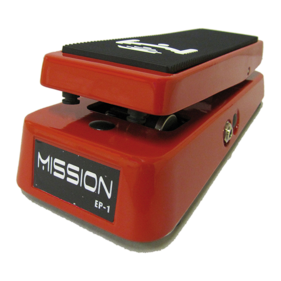
Congratulations on your purchase of the Mission
expression pedal. This product is designed to be
intuitive to setup and operate, and to provide
many years of trouble free service. However, we
recommend that you take a few moments to read
through this User Guide in order to get the best
possible experience with your new pedal.
ING
fê tur
This guide covers the following Mission model
numbers: EP-1, EP1-R, SP-1, SP1-R
The EP-1 and SP-1 are professional quality, all
metal expression pedals designed for use with TRS
expression pedal inputs on a wide variety of digital
amplifiers, effects, MIDI controllers and stomp
boxes. The -R models feature a polarity switch for
compatibility with a wide range of different devices.
The SP-1 models feature a second output connected
to a toe switch. The switch can be used with
compatible devices to support switchable functions
such as turning an effect on and off.
pow
The EP-1 and SP-1 pedals are passive devices and
require no internal battery or external power source
for expression control and switching. If your SP-1
is fitted with the optional LED indicator, an internal
9v battery is required to power the LED only. If the
battery is removed, the pedal will still function, only
the LED will be disabled.
odu
ion
ConnE
ions
The EP-1 uses a single ¼" TRS phone plug outputs
marked OUT1 on the underside of the pedal.
Connect OUT1 to the expression pedal input on your
device using a ¼" TRS-TRS instrument cable such
as the Mission MCTRS3A cable. TRS stands for
Tip, Ring, Sleeve and is a three-conductor cable. It
is sometimes also called a stereo or balanced cable.
OUT1 requires the use of the correct cable with a
TRS connector at both ends. A mono TS cable such
as a regular guitar cable, and insert cables that have
both TS and TRS plugs, will not work in most cases.
Figure 1.
Figure 1. A TRS connector with the three conductors
separated by the black insulation bands. The pointed
front of the connector is the tip, the middle band is
the ring, and the large conductor at the rear nearest
the plug body is the sleeve.
The SP-1 features an additional output labeled
OUT2 that provides toe switching functions when
used with a compatible MIDI controller. Use of
the footswitch is optional. To use the footswitch,
connect OUT2 to a compatible input 2 on the
controller using a second TRS-TRS ¼" instrument
cable. The switch is operated by pushing down on
the front of the pedal with sufficient pressure to
actuate the switch.
no
The standard SP-1 is fitted with a TRS latching
foot switch. Different controller inputs may require
different switches. The SP-1 is interchangeable
between different types. User installable Switch
Kit's are available from missionengineering.com
Advertisement
Table of Contents

Summary of Contents for Mission EP-1
- Page 1 ConnE ions Congratulations on your purchase of the Mission The EP-1 uses a single ¼” TRS phone plug outputs expression pedal. This product is designed to be marked OUT1 on the underside of the pedal. intuitive to setup and operate, and to provide Connect OUT1 to the expression pedal input on your many years of trouble free service.
- Page 2 © Mission Engineering Inc. 2013. All rights reserved. EP-1, EP1-R, - the unit does not operate normally or changes SP-1 and SP1-R are Trademarks of Mission Engineering Inc. press. When replacing the switch, be careful not to...
Need help?
Do you have a question about the EP-1 and is the answer not in the manual?
Questions and answers