Table of Contents
Advertisement
PLEASE KEEP THESE INSTRUCTIONS FOR FUTURE REFERENCE
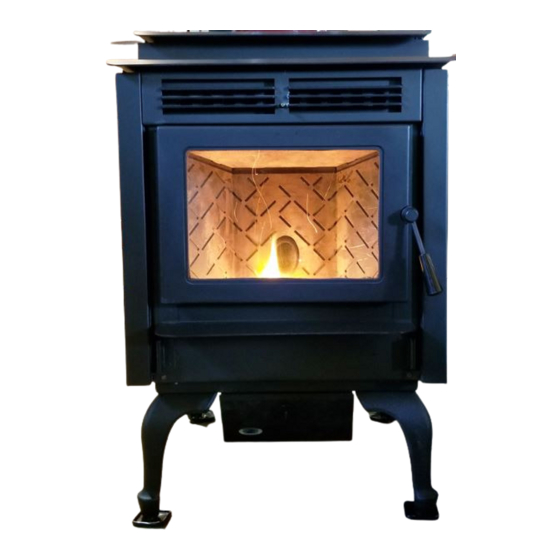
PELLET STOVE
DAVENPORT
Freestanding and Fireplace Insert
OWNER'S MANUAL
Contact your building or fire officials about restrictions and installation inspection
requirements in your area.
PLEASE READ THIS ENTIRE MANUAL BEFORE INSTALLATION
AND USE OF THIS PELLET-BURNING ROOM HEATER. FAILURE TO
FOLLOW THESE INSTRUCTIONS COULD RESULT IN PROPERTY
DAMAGE, BODILY INJURY OR EVEN DEATH.
16621
THIS MANUAL IS PRINTED ON RECYCLED PAPER.
50-2322
Advertisement
Table of Contents

Related Manuals for Hudson River Stove Works DAVENPORT


Summary of Contents for Hudson River Stove Works DAVENPORT
- Page 1 PLEASE KEEP THESE INSTRUCTIONS FOR FUTURE REFERENCE PELLET STOVE DAVENPORT Freestanding and Fireplace Insert OWNER’S MANUAL Contact your building or fire officials about restrictions and installation inspection requirements in your area. PLEASE READ THIS ENTIRE MANUAL BEFORE INSTALLATION AND USE OF THIS PELLET-BURNING ROOM HEATER. FAILURE TO FOLLOW THESE INSTRUCTIONS COULD RESULT IN PROPERTY DAMAGE, BODILY INJURY OR EVEN DEATH.
-
Page 2: Table Of Contents
Table of Contents ......................3 introduction ....................3 rating label location ......................3 pellet quality ....................4 important safety data ................4 safety warnings and recommendations & ......................6 dimensions specifications ....................6 dimensions freestanding ..................6 dimensions fireplace insert ..................6 s p e c i f i c at i o n s ....................7 i n s ta l lat i o n ..............7... -
Page 3: Introduction
Since Hudson River Stove Works has no control over the quality of pellets that you use, we assume no liability for your choice in wood pellets. -
Page 4: Important Safety Data
Introduction mPoRtant afety Please read this entire Owner’s Manual before installing or operating your HUDSON RIVER Pellet Stove. Failure to follow these instructions may result in property damage, bodily injury or even death. Contact your local building or fire official to obtain a permit and any information on installation restrictions and inspection requirements for your area. - Page 5 If you have any questions with regards to your stove or the above-mentioned information, please feel free to contact your local dealer for further clarification and comments. SINCE HUDSON RIVER STOVE WORKS HAS NO CONTROL OVER THE INSTALLATION OF YOUR STOVE, HUDSON RIVER STOVE WORKS GRANTS NO WARRANTY IMPLIED OR STATED FOR THE INSTALLATION OR MAINTENANCE OF YOUR STOVE.
-
Page 6: Dimensions & Specifications
Figure 1: Davenport Freestanding Dimensions. imenSionS iRePLace nSeRt 25 5 8 " 22" 8 " 22 3 4 " Figure 2: Davenport Fireplace Insert Dimensions. PecificationS Input rating: 42,500BTU Table 1: Davenport Specifications. Description Fuel type Residential Pellet Heater 6mm (¼”) dia. Wood Pellets... -
Page 7: Installation
Installation eciDing heRe to ocate youR eLLet PPLiance 1. Check clearances to combustibles (see i nstallation learances to ombustibles , and i reestanding nstallation lcove learances reestanding nstallation learances to ombustibles ireplace nsert 2. Do not obtain combustion air from an attic, garage or any unventilated space. -
Page 8: Clearances To Combustibles - Freestanding
9” MINIMUM Figure 5: Minimum Clearances to Combustibles for Freestanding Figure 4: Davenport on Floor Protection. Davenport. This pellet stove requires floor protection. The floor protection must be non-combustible, extending beneath the stove the full width and depth of the unit including 9“ in front for ember protection. -
Page 9: Clearances To Combustibles - Fireplace Insert
Installation LeaRanceS to ombuStibLeS iRePLace nSeRt The fireplace insert must be installed into a masonry fireplace. This model includes a surround faceplate and a pedestal. From the body of the heater to the side wall: 9 inches minimum From the body of the heater to the Facing on masonry fireplace: 8 inches minimum From the body of the heater to the 10”... -
Page 10: Vent Termination Requirements
5. If the unit is incorrectly vented or the air to fuel mixture is out of balance, a slight discoloration of the exterior of the house might occur. Since these factors are beyond the control of Hudson River Stove Works, we grant no guarantee against such incidents. -
Page 11: Exhaust And Fresh Air Intake Locations
4 " 1" 4 " 8 " 1" Figure 9: Davenport Inlet and Outlet Location. INSTALL VENT AT CLEARANCES SPECIFIED BY THE VENTING MANUFACTURER utSiDe ReSh onnection Outside fresh air is mandatory when installing this unit in airtight homes and mobile homes. -
Page 12: Corner Through Wall Installation - Freestanding
Installation oRneR hRough nStaLLation ReeStanDing Fresh Air Intake 3" (7.5 cm) Wall thimble manufactured by pellet vent manufacturer. 3" (7.5 cm) Figure 12: Corner Installation. oRizontaL xhauSt hRough nStaLLation ReeStanDing Vent installation: install vent at clearances specified by the vent manufacturer. A chimney connector shall not pass through an attic or roof space, closet or similar concealed spaces, or a floor, or ceiling. - Page 13 Installation 10. The pipe must extend least 12” (30 cm) away from the building. If necessary, bring Exhaust Tube another length of pipe (PL type) to the 3" (75mm) or 4" (100mm) "PL" or "L" vent outside of the home Wall Thimble to connect to the first section.
-
Page 14: Vertical Rise With Horizontal Termination Installation - Freestanding ( Recommended )
Installation ) - f eRticaL iSe With oRizontaL eRmination nStaLLation ecommenDeD ReeStanDing Termination cap 90°elbow Wall framing A 45° elbow with a rodent screen may be used in place of the termination cap (or stainless steel Vertical section of vent pipe termination hood). -
Page 15: Inside Vertical Installations - Freestanding
Installation nSiDe eRticaL nStaLLationS ReeStanDing 1. Choose a stove location that is ideal. See the section “i nstallation eciding here to ocate your ellet .” ppliance 2. Place unit Rain cap - ensure cap is at hearth pad (if installed on least 2 feet (610mm) above a carpeted surface) and the roof at the lowest point... -
Page 16: Outside Vertical Installations - Freestanding
Installation utSiDe eRticaL nStaLLationS ReeStanDing To accomplish a outside vertical pipe installation, follow steps 1 through 5 in the “i nside ertical nstallations ” section and then finish it by performing the following (refer to Figure 23). reestanding 1. Install a tee with clean out on the outside of the house. 2. -
Page 17: Hearth Mount Installation - Freestanding
Installation eaRth ount nStaLLation ReeStanDing Damper Removed Rain cap or Fastened Open Mantel Minimum 8" (20 cm) from top of stove NOTE: Hopper lid will not open fully with less than 13.5”. Storm collar Clean-out tee Min 9" Fresh-air intake should Seal plate come from chimney. -
Page 18: Masonry Fireplace Installation - Fireplace Insert
Installation aSonRy iRePLace nSeRt nStaLLation iRePLace nSeRt The Fireplace insert model requires a surround faceplate and a pedestal. When installing this unit, ensure that the pedestal is removed from the inside of the hopper and installed on the bottom of the unit (Refer to i nstallation nstallation of... -
Page 19: Positive Flue Connection Without A Full Reline - Fireplace Insert ( Usa Only )
Installation (uSa o oSitive onnection Without a eLine iRePLace nSeRt This unit does not require a full reline (in USA only) when installing into a masonry fireplace, however, it is recommended to ensure proper drafting of the appliance. IMPORTANT: Ensure the chimney and firebox are cleaned and free of all debris, including soot and ashes, before proceeding with this installation. -
Page 20: Installation Of The Control Panel In The Surround Panel - Fireplace Insert
Installation nStaLLation of ontRoL aneL in uRRounD aneL iRePLace nSeRt Tools Required: Torx T-20 Screwdriver 1. Remove the control panel from the shipping position on the unit by removing one 8-32 x 3/8” Torx screw. 2. Align the control panel with the two holes in the surround panel and fasten using two (2) 8-32 x 3/8”... -
Page 21: Thermostat Installation
Installation heRmoStat nStaLLation 1. Install the wall thermostat in a location that is not to close too the unit but will effectively heat the desired area. 2. Install a 12 or 24 Volt Thermostat using an 18 x 2 gauge wire from the unit to the thermostat. If the unit has been placed in the HI / LOW mode, the unit will be taken to a low or idle setting when the thermostat is not calling for heat. -
Page 22: Operating Instructions
Operating Instructions ontRoL oaRD unctionS 1. AUGER LIGHT: This green light will flash in conjunction with the auger pulse. 2. MODE LIGHT: Responsible for signaling the state of the control board. When the light is flashing the stove is in an automatic start mode or the thermostat has control of the unit. When the light is solid, the Heat Level Setting can be altered. -
Page 23: Turning Your Pellet Stove Off
Operating Instructions AUGER AUGER MANUAL MODE: MODE MODE All control of circuit board function is adjusted at the circuit board. To START: Press the ON / OFF button. The stove will turn on. The AUTO/OFF AUTO/OFF system light will flash. The Auger Light will flash with each pulse of the HIGH/LOW HIGH/LOW MANUAL... -
Page 24: Adjusting The Vacuum Using The Slider Damper
Operating Instructions LiDeR amPeR THE SLIDER / DAMPER MUST BE SET AT TIME OF INSTALLATION. A Qualified Service Technician This is used to regulate the airflow through the pellet stove. The or Installer must set the Slider Damper. slider damper knob is located on the left cab side (see Figure 7). If the fire should happen to go out and the heat output indicator has been set on the lowest setting, the Slider Damper should be pushed in slightly, decreasing the air in the firebox. -
Page 25: Routine Cleaning And Maintenance
Routine Cleaning and Maintenance The following list of components should be inspected and maintained routinely to ensure that the appliance is operating at its optimum and giving you excellent heat value: 2-3 Days / Weekly Semi-annually or 2 Tons of Fuel Burn Pot and Liner Exhaust Vent Ash Pan... -
Page 26: Routine Cleaning And Maintenance
Routine Cleaning and Maintenance ASH PAN AND DOOR GASKETS (weekly) After extended use the gasketing may come loose. To repair this, glue the gasketing on using high- temperature fiberglass gasket glue available from your local HUDSON RIVER dealer. This is important to maintain an airtight assembly. -
Page 27: Routine Cleaning And Maintenance
Routine Cleaning and Maintenance (season) EXHAUST PASSAGES Removal of the firebox backing for bi- annual cleaning (refer to Figure 10): • Open the door by lifting the handle, remove the burn pot and burn pot liner. • Lubricate all screws with penetrating oil. •... -
Page 28: Troubleshooting
Troubleshooting DO NOT: ● Service the stove with wet hands. The stove is an electrical appliance, which may pose a shock hazard if handled improperly. Only qualified technicians should deal with possible internal electrical failures. ● Remove any screws from inside the firebox without first applying a penetrating oil lubrication. WHAT TO DO IF: 1. - Page 29 Troubleshooting Check Vacuum levels in the exhaust channel by bypassing the Vacuum Switch, then remove the Vacuum hose from Vacuum Switch. Check exhaust vacuum readings by placing the open end of the Vacuum Hose on a Magnahelic Gauge (readings must be above .10” W.C. on low fire). If the motor fails to reach a 0.10”...
- Page 30 Troubleshooting 6. The 200 °F ( 93 °C) high limit temperature sensor has tripped. Reset sensor and determine cause – was it Convection Blower failure or 160 °F ( 71 °C) Temperature Sensor failure? Bypass the 160 °F ( 71 °C) sensor, does the Convection blower come on high if not replace the blower? If yes, replace sensor (located on the left side of the firewall).
-
Page 31: Wiring Diagram
Wiring Diagram Grey Vacuum Grey Switch White Combustion Blue Brown Blower Exhaust Temperature Sensor Power Cord Brown Ground Black 115V 115V White Black Black White Thermostat Common 5 Amp Ignitor Fuse Convection Temperature Black Sensor White Orange Orange Purple Purple Convection Blue White... -
Page 32: Parts Diagram Fs
PARTS DIAGRAM - FS... -
Page 33: Parts Diagram Fpi
PARTS DIAGRAM - FPI... -
Page 34: Parts Diagram Options
PARTS DIAGRAM - OPTIONS... -
Page 35: Parts List
OPTION 50-2224 HUDSON RIVER FS LEG KIT 50-2322 DAVENPORT OWNERS TECHNICAL MANUAL 50-2323 DAVENPORT FS HOPPER LID (OLD SERIALIZED PART MUST BE RETURNED) 50-2324 DAVENPORT FPI HOPPER COVER (OLD SERIALIZED PART MUST BE RETURNED) 50-2325 DAVENPORT FS TOP 50-2326 DAVENPORT FPI HOPPER LID... - Page 36 EC-001 120F (49C) Ceramic Fan Temperature Sensor EC-042 DOMESTIC POWER CORD 115V EC-044 HEYCO STRAIN RELIEF EC-054 1 X 1 CABINET SIDE HINGE (1) EC-058 WINDOW CHANNEL TAPE- 72IN EF-001 AUGER MOTOR 1 RPM EF-002 CONVECTION BLOWER 115V EF-004 CONVECTION BLOWER IMPELLER EF-006 CONVECTION BLOWER INSULATOR (GASKET) EF-008...
-
Page 37: Warranty
Warranty Limited Lifetime Warranty: Under this warranty, Hudson River Stove Works covers the body of the stove including all exterior metals. This warranty covers: Firebox, Heat Exchanger, Pedestals, Legs, and Door Assembly. Please see the exclusions and limitations section below as certain restrictions and exclusions apply to this warranty. -
Page 38: Installation Data Sheet
DATE OF PURCHASE: _____________ (dd/mm/yyyy) DATE OF INSTALLATION:___________ ADDRESS: (dd/mm/yyyy) MAGNEHELIC AT INSTALL:___________________ _________________________________________ INSTALLER’S SIGNATURE: _________________________________________ _________________________________________ _________________________________________ PHONE:___________________________________ MANUFACTURED FOR HUDSON RIVER STOVE WORKS BY: SHERWOOD INDUSTRIES LTD. 6782 OLDFIELD RD. SAANICHTON, BC, CANADA V8M 2A3 August 27, 2010 C-12242...
Need help?
Do you have a question about the DAVENPORT and is the answer not in the manual?
Questions and answers